Just for interest,
Thought I would post this before the article falls apart..
From the back of the cupboard.
Regards
M. Gregg
Thank you for posting this.
")
I hate being such a pedantic … but after you replace all the capacitors and resistors, and 'work through' the issues of all of them being fundamentally different parts, knowing full well that the modification of any one of them significantly might affect the tonal nature of the amplifier(s) being restored … aren't you defying entirely the purpose of said restoration?
FOR INSTANCE - all those carbon comp resistors that are original, will have varied less than 1% from their original soldered-in values due to ageing. Why bother change them? Are they coated with sticky oils and nasty mouse poo? Its not like you're going to change out the little transistors and other components on the boards. Nor the boards, which will be covered in the same sticky oils and mouse poo. Just saying.
Nor do I see a reason to change out the cylindrical axial-lead capacitors of low value, high volts. They don't spontaneously develop pinholes while sitting at the bottom of a can't-bear-to-throw-it-away shelf for decades. The electrolytics one can reasonably make an argument to swap. Their electrolyte can (and often does) dry out, and the components of the electrolyte can very gradually degrade the insulation resistance of the aluminum-oxide dielectric, over time. Fine! But seriously, hermetically tight, entirely dry, film capacitors?
You might get away (with me) of declaiming: “well, they were a lousy dielectric, and well known to be one of the fundamental sonic limitations of the amplifiers”. OK, you're doing a restoration and an upgrade. I get that.
But the resistors? Really?
Rant: OFF
GoatGuy
I would have thought that the carbon comp resistors are quite likely to have drifted. I have measured CC resistors from the 1950s which are 50% off the marked value.GoatGuy said:FOR INSTANCE - all those carbon comp resistors that are original, will have varied less than 1% from their original soldered-in values due to ageing. Why bother change them?
It all depends on what dielectric they used, and how well sealed they are. Paper dielectric caps often need replacing in old equipment.Nor do I see a reason to change out the cylindrical axial-lead capacitors of low value, high volts. They don't spontaneously develop pinholes while sitting at the bottom of a can't-bear-to-throw-it-away shelf for decades.
RE DF96 and JOHNM, and drift of resistor values. Here's something, which few people have had the equipment … and time … to note:
Back in the 1960s I was avidly studying precision metrology, and was on a hêll-bent course to find top-shelf metrology equipment and various standards that might give me the ability to measure resistance, voltage, current, capacitance, inductance and even incipient electric fields to better than 10 ppm accuracy. I thought it would be easy. It wasn't.
Eventually, I got ahold of a Honeywell Model 1071 Wheatstone bridge, along with a number of oil-filled certified resistance standards… you know, 1 Ω ("The King"), 10, 100, 1000. And for some reason that I never heard a convincing story for, I also had a Kelvin-Nodle 72,143 Ω certified standard. The lower ones were all temperature compensated over a ±10°C range centered at 20°C.
Having mastered the math and metrology, and being well armed with a 5+ digit logarithms table (amongst other things) from a deceased 1930s electrical engineering uncle, I proceeded to accurately measure every resistor I had in my collection, and to affix little strips of paper (stapled!) to each of them for permanent reference. Its a whole lot easier to measure a bunch at a time and write the values down, than to have to haul everything out and do it as needed.
Then I discovered those vexing critters: girls
Well, electronics took the back seat significantly. I put all the resistors and mica capacitors, and all the various paper, oil, poly and yes Bad Boy Mylar caps (dutifully measured), into a great chest. It got buried. From time to time I embarked on a project, and rooted out various values. It was kind of silly to have 4+ digit resolution on all the values, but I was honing a skill, not doing anything really practical.
Then I lost track of the whole lot.
We just got around to emptying out "Mom's Basement", and the old chest was there, little scripts of paper intact. I thought, “before I give all this away to that earnest youngster down the street, I wonder how much some of the values have changed”, since it is a hotly contested issue. So, I measured several score resistors, capacitors and inductors.
No surprise, really: the inductors seem to never age. Leakage still in the high, high MΩ. Series resistance essentially constant. Inductance was never 5+ digits, but more like 3- … with frequency-pass being the weak link. Still … no change.
Capacitors were just about the same, except for the electrolytics. The E-C's were quite different from the values measured 50 years back. None of them had been in service, but were just sitting in a nice dry, nearly constant temperature locked chest. Chemistry, was my surmise.
Resistors were 95% of the time "right on the dot" as to when they were measured in 1966. Very little drift. For the Allen-Bradley brand, less than 0.5%. For others, more. For the big chunky 1940s and early 1950s "crude resistors" of the carbon-comp type, there was more variability. My surmise: permeable casings allowing moisture in, and transpiration of oxygen. Enough of that, over the 50 years, and they varied up to 8%. There was one that varied 23%. But only 1 of hundreds. I chucked it. Actually, I chucked most of the old-style resistors. Ugly.
The point of the story though is this: I do not concur with the premise that resistors vary 50%.
HOWEVER (and this is 'the point')… the most unamusing thing I found - back in 1966 - was that the older resistors often varied from their stated binning by way more than their hopefully applied tolerance band color. Remember: no 4th band was ±20%, silver was ±10%, gold was ±5%. The ones with NO 4th band were more like ±33%, when comparing the resistance value "as painted on" versus that measured in 1966.
Perhaps that's the systemic "error-in-thinking" that has given legs to the notion that when measuring resistors today, it is probable to fine "drift" of 35% or more. Because the original values were equally adrift.
Sobering.
Few of us weren't taking and recording 4–5 digit accuracy in 1966.
I was just enough of an 'early model geek' to do so.
GoatGuy
I've used metal film 1w resistors.
Amp number one is done and currently warming the room. Think I have at least 2 duff kt66 valves and possibly a bad rectifier.
The bakerlite base is loose on one of the KT66s and it creates all kinds of noise....
Another acts like a lighthouse with a winking bright spot. Very festive. It also creates quite a fuss.
Fairly sure one of the rectifiers was causing one of the good valves to red plate.
Any rate, 69183 is now running nicely and singing folk songs to me.
I'll overhaul the second amp if I get time tomorrow but I'll need some more valves before I get to hear them in stereo.
Diverting somewhat: Re keeping classics:
I thought the main idea was 'collecting' because it is a classic; representative of the best of an era, value in rarety and such. Use ... secondary goal? My Gran had several salt cellars from an era, rare, and not to be used because of risk of damage. Vintage cars, stamps, name-it? Obviously the choice of the collector, but if crazy then there are a lot of crazy folks on earth.
Yes, possibly counter to restoration. But if possible to bring back to operation by replacing a few components without changing the basic design .....
That is the very point we perhaps agree on. The article quoted by M Gregg and several others of the same nature: Rather no comment, except for saying that that sort of stuff often illustrates what not to do. It mostly reveals the writer's fixation that the 'better' the component the more the sonic advantages ... naturally energetically supported by merchants of said components. After restoration and some inevitable design improvements (the original designer was an imbecile) - lo and behold! The expected dramatic improvement in all manner of characteristics that have nothing to do with electronics, only revealing the writer's ignorance of electronic basics. I.e. self-condemning. Not to repeat detail; GoatGuy has said it.
P.S: The often mentioned 'poor quality' Quad 22 pre-amp. That is mostly the result of unexplained change in value (as in up to >2x) of 12 styrene caps in tone-shaping circuitry. The design itself was a particularly good one for the time and for today regarding tubes. If someone is convinced it is useless, take advantage, buy at a low price and restore.
The bakerlite base is loose on one of the KT66s and it creates all kinds of noise....
If the space between glass and previous seal is not too big, an easy way to reseal is by simply allowing acetone (thinner) to flow in - sparingly! The old sealant is not soluble in acetone, but it does seem to 'soften' it sufficiently to restick. Super clue (cyano-acrelate) is tempting, but there has been an alarming number of reports that the glass cracks at the seal line. The maximum temperature is also too low for power tubes. Other materials like automotive silicone and Araldite have been used.
If the 'looseness' caused a noise on the output, resoldering the leads in the base pins might help.
Another acts like a lighthouse with a winking bright spot. Very festive. It also creates quite a fuss .... Fairly sure one of the rectifiers was causing one of the good valves to red plate.
If the KT66 is shot anyway, then .... But not sure how the rectifier could have caused red-plating. Hopefully cured by the new components.
For what it's worth, the carbon comps that I pulled were (as many have found) in excess of 10% out in many cases. Not to mention the awful temperature coefficient characteristics of carbon resistors; this being my main motivation for going metal film.
I'll see what can be done to try and save the wobbly valve and the other winking christmas tree valve after getting the other amp restored.
I'm going to give all the valve bases a good blast of deoxit and clean them through as well to make sure bitumen grease and mouse poo isn't causing poor contacts with the valves.
Last edited:
P.S: The often mentioned 'poor quality' Quad 22 pre-amp. That is mostly the result of unexplained change in value (as in up to >2x) of 12 styrene caps in tone-shaping circuitry. The design itself was a particularly good one for the time and for today regarding tubes. If someone is convinced it is useless, take advantage, buy at a low price and restore.
I'm planning to sell the 22 I have, mainly as I have a good valve RIAA pre already and I don't want to stress the Quad's by running it off them.
People back then had meters and the ability to use them. Let's not fall into temporal snobbery. The lack of drift of your CC resistors is probably due to them sitting in a drawer, not experiencing regular temperature cycling.GoatGuy said:Perhaps that's the systemic "error-in-thinking" that has given legs to the notion that when measuring resistors today, it is probable to fine "drift" of 35% or more. Because the original values were equally adrift.
Do you mean 10% from marked value, or 10% outside tolerance? In either case, this is fine - no need to replace them. The originals would probably have been mainly 20% tolerance. Valve circuits are not fussy about exact resistor values (apart from RIAA networks).Katch said:For what it's worth, the carbon comps that I pulled were (as many have found) in excess of 10% out in many cases.
Limbering up... Quad 303 resurrected from the grave. It had no output on either channel. Replaced the PSU caps (output caps on back-order...), the electrolytics on both channels and replaced all the trimmers.
An externally hosted image should be here but it was not working when we last tested it.
Just letting it burn in for an hour or so before resetting the bias. Gonna be using a pair of these to biamp my system while I get these Quad IIs back up.
.....
A bit off topic ....
Your 303 looks like an early version. What is the serial number ?
Andy
A bit off topic ....
Your 303 looks like an early version. What is the serial number ?
Andy
That one is just into the new revisions at 15xxx can't remember exactly but you can see the bias pots are in the revised positions.
69781 is alive and well.
2 KT66s are not, one spectacularly so. Think I'm lucky I pulled the plug nice and quickly. Shame, as they were original GEC valves and there's no way I can afford to replace them with the same.
Going to pick up a quad matched set of Russian or Chinese KTs for them. The other rectifier seems fine. Must have just been the two bad tubes.
69781 is alive and well.
2 KT66s are not, one spectacularly so. Think I'm lucky I pulled the plug nice and quickly. Shame, as they were original GEC valves and there's no way I can afford to replace them with the same.
Going to pick up a quad matched set of Russian or Chinese KTs for them. The other rectifier seems fine. Must have just been the two bad tubes.
I've been using these KT66 from PM Components, they are the Golden Dragon brand and sound very good in my Quad II's and Leak TL12.1's.
KT66 audio tetrode | eBay
They will match them for free aswell.
Sharif.
I agree with Johan's suggestion of repairing loose valve bases with infusing some acetone to re-activate the original adhesive. If I were to do this, I would also rotate the envelope clock and counter clockwise with minute movements only as far as the envelope wires allow. This in order to 'spread' the acetone evenly. This will be a careful, delicate repair in order to avoid not breaking pin wires.
After this procedure, I would also tape up the glass envelope crosswise from the tube's top to the tube's pins with masking tape and allowing the remoisturised original adhesive to set properly for a few days before use. Two suitable elastic bands can also be used inplace of the masking tape.
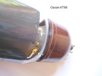
Before Johan posted his acetone method, I had the same problem (loose bases) with two Osram KT66'es but I used slow setting Araldite (no affiliation) to re-glue.
I carefully cleaned out all loose old adhesive using a watchmakers broach (something like a very slender steel spike). Afterwards, I blew out loose particles between the base and glass and mixed up some Araldite.
I worked the epoxy into the gap, using a sharpened and thinned bamboo toothpick and wiped off the excess with a barely damp lintfree cloth and a bit of lacquer thinners.
Slow setting Araldite will take several days in moderate temperatures to set really hard after about 4 to 5 days.
Here you can see the result.
bulgin
After this procedure, I would also tape up the glass envelope crosswise from the tube's top to the tube's pins with masking tape and allowing the remoisturised original adhesive to set properly for a few days before use. Two suitable elastic bands can also be used inplace of the masking tape.
Before Johan posted his acetone method, I had the same problem (loose bases) with two Osram KT66'es but I used slow setting Araldite (no affiliation) to re-glue.
I carefully cleaned out all loose old adhesive using a watchmakers broach (something like a very slender steel spike). Afterwards, I blew out loose particles between the base and glass and mixed up some Araldite.
I worked the epoxy into the gap, using a sharpened and thinned bamboo toothpick and wiped off the excess with a barely damp lintfree cloth and a bit of lacquer thinners.
Slow setting Araldite will take several days in moderate temperatures to set really hard after about 4 to 5 days.
Here you can see the result.
bulgin
Attachments
Last edited:
Replacement set of KT66s arrived today, so finally got to hear these running. They sound lovely.
Next job is to fit some proper speaker binding posts, fused and switched IEC power socket and RCA inputs. Then I'm done for now. I'll listen to them for a while and decide if I'm keeping them long term or not. If they're staying, I'll probably chrome or respray them.
Next job is to fit some proper speaker binding posts, fused and switched IEC power socket and RCA inputs. Then I'm done for now. I'll listen to them for a while and decide if I'm keeping them long term or not. If they're staying, I'll probably chrome or respray them.
I guess I'm on the final straight with these now. IEC power inlets have arrived. I've removed the Jones connectors and stripped out the associated HT and heater wires. Just waiting on some speaker binding posts to arrive from China.
Last couple of questions.
Should I add capacitors to the inputs? If so what flavour? Do I keep the 1.5M resistor in parallel?
What's a good choice for the 0.1uf caps I need to use to mitigate the lost capacitance from the old metal can PIO caps?
Last couple of questions.
Should I add capacitors to the inputs? If so what flavour? Do I keep the 1.5M resistor in parallel?
What's a good choice for the 0.1uf caps I need to use to mitigate the lost capacitance from the old metal can PIO caps?
- Status
- This old topic is closed. If you want to reopen this topic, contact a moderator using the "Report Post" button.
- Home
- Amplifiers
- Tubes / Valves
- My Quad II and 22 restoration