Ha ha, putting a resistor in series with the B+ more like creating sag upon large signal that people like the tube rectifiers. I did put a low value resistor just for that, not really for dropping the voltage and for better filtering.
I have not found lots of filter cap help in guitar amp, I read from somewhere that too much filter cap does not even help guitar amp. I'll let Enzo talk about it in more detail as he has a lot more experience.
Sag is bad for audiophile, it's a good thing for guitar amp. Many of what it's good for audiophile is not good for guitar amps. they are apple and orange.
A stiff power supply is not a good thing for guitar amps at all. I found guitar amp with SS rectifier ( stiffer) sounds to stiff for me, I like my Pro Reverb that has tube rectifier that gives me the extra sag. It's too much work to put the tube rectifier, so I used SS for my design, then use a resistor to give some extra sag.
Last edited:
I started with the RSGB Handbook in 1971, but nowadays I would use PSUD2 to model the PSU.steeledriver said:I'll look for more literature when I'm home from work, but in the mean time, what design guides or manuals for selecting power transformers have been most helpful to you?
Either you misunderstood him, or he is not a guru. It is not the filter which determines the relationship between DC current draw and AC secondary RMS needs, but the first element: C or L?Bob Richards said:A tube guru friend of mine told me that the current draw of a multisection RC filter in the power supply will approximately double the load seen by the power transformer. I don't know if that's exactly true, but it did make me aware that I had forgotten to consider that at all. In use, those caps are constantly needing to be recharged.
A capacitor input filter will need a factor of 2-3 between DC and AC current, regardless of what smoothing follows it.
The 6.5V filament at 3.15A is too low. Plenty of HV current that is not necessary as guitar doesn't not produce continuous signal. But filament burns continuously. Also, 6.5V??!!
Or else, it's good price for no shipping. Maybe look for a small 6.3V transformer to supplement it.
I was somewhat banking on the idea of the slightly higher current draw dropping the supply voltage slightly, getting it closer to 6.3.
The next step up was 5A on the 6.3V winding, but much larger - rated 320-0-320 at 518mA.
http://www.hammondmfg.com/pdf/EDB290FX.pdf
I was somewhat banking on the idea of the slightly higher current draw dropping the supply voltage slightly, getting it closer to 6.3.
The next step up was 5A on the 6.3V winding, but much larger - rated 320-0-320 at 518mA.
http://www.hammondmfg.com/pdf/EDB290FX.pdf
You have to think about this as guitar amp, this one is for very high power like 100W+, it is going to be very stiff and very little sag. This is like using a PT from Twin Reverb and only use two 6L6. It's going to be heavy and might not sound as good.
Guitar amp is different from audiophile, in audiophile, we want as big a transformer as possible and the supply as stiff as possible for low distortion. In guitar amp, you want sag and distortion!!! Most of the things you learn here.....think opposite. Your main thing is to make sure the power transformer won't burn and don't over size it. this hold true in OT also.
I am surprised Hammond make it so imbalanced, so much current for B+ but not enough for filament. Don't think filament power is not important, it really can heat up the transformer. I remember back in the 70s when I first did a power scaling using a variac, I had to put the filament on separate 6.3V transformer so the voltage didn't vary with the variac. The transformer felt a lot cooler without the filament load.
Last edited:
You have to think about this as guitar amp, this one is for very high power like 100W+, it is going to be very stiff and very little sag. This is like using a PT from Twin Reverb and only use two 6L6. It's going to be heavy and might not sound as good.
Guitar amp is different from audiophile, in audiophile, we want as big a transformer as possible and the supply as stiff as possible for low distortion. In guitar amp, you want sag and distortion!!! Most of the things you learn here.....think opposite. Your main thing is to make sure the power transformer won't burn and don't over size it. this hold true in OT also.
I am surprised Hammond make it so imbalanced, so much current for B+ but not enough for filament. Don't think filament power is not important, it really can heat up the transformer. I remember back in the 70s when I first did a power scaling using a variac, I had to put the filament on separate 6.3V transformer so the voltage didn't vary with the variac. The transformer felt a lot cooler without the filament load.
I suspect the imbalance has to do with the fact that it's a replacement transformer for the 50W Bassman. My amplifier is around 40W - which is why it looked promising - but I have an extra preamp tube or two. I wasn't too keen on the 290FX because of its very high current rating. I want this amplifier to spend most of its time on the border between clean and slightly overdriven, so I don't want the power supply to be too stiff.
On paper, I'm only slightly exceeding the rated current on the heater windings. It might be worth seeing if it is a problem in practice. If it is, for about $10, I could get a 6.3V or 12.6V transformer that can run all of my 12AX7s instead of running them on the 290EX. I might pick one of those up as a precaution. A 12.6V transformer would also drop my preamp heater current and lead to less heater noise.
There's also a $20 upgrade - the 291EX. The datasheet for it is exactly the same as for the 290EX, so I'm not sure what the difference is.
Last edited:
I don't see any difference of the upgrade. From what I seen and heard, hammond over kill with big iron core, get the cheaper one. Buy the small filament transformer and it still be the cheapest for you. don't get the huge one, your back will thank you when you go gigging.
When I was young, I was worry about the OT is too small, I changed to the Bassman 100 huge OT, it did not sound good.
My amps are channel switching cascade gain switchable from 3 stages to 4 stages. Noise is of utmost important. I use schottky diode to rectify the 6.3V to get DC filament. It helps lowering the noise. Just an idea.
You might want to experiment a resistor in series from the output of the SS rectifier of B+ to the reservoir cap ( the first stage filter before the choke or the screen grid. Experiment at high volume and find a value that gives you some sag. We had a discussion in the other forum, it simulate a tube rectifier to a big extend.
Too bad you are so far away, I have two of the imbalance Weber sitting in the shed. I hate to dump it, but I am not going to open it and try to take off some turns to balance the voltage. Particularly if the turns are under the filament winding. That's made in China for you.
Last edited:
You might want to experiment a resistor in series from the output of the SS rectifier of B+ to the reservoir cap ( the first stage filter before the choke or the screen grid. Experiment at high volume and find a value that gives you some sag. We had a discussion in the other forum, it simulate a tube rectifier to a big extend.
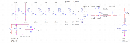
I'm planning on doing that once I see how much spare B+ I have, to see how much I can drop for sag. That'll come after I buy the transformers. Right now in my design I've got 10 Ohm resistors in series with the B+ and ground paths, connected by a bleeder, to get one extra filtering stage before my plates and minimize ground hum.
I've decided to go for a 4.25k:8 output transformer (Hammond 1750JA). It's about the best I can do locally within my budget, although I'd prefer something around 5k. I can always play with my screen voltage to change where the load line passes through the knee of the plate curves.
I hadn't planned on rectifying the heaters unless noise is a problem in the amp - I've got a humdinger creating an artificial center tap to reduce noise for now.
Thank you for considering sending your Weber over, I appreciate the thought. Getting things shipped from the U.S. to Canada is a big pain - especially something as heavy as a transformer. Hell, I haven't found somewhere in Canada that stocks reverb tanks - and the shipping on those from the U.S. is more expensive than the tanks themselves!
Attachments
Last edited:
Off hand, I think 4.25k primary is what you want. You have 330V-0-330V, which gives you 466V after rectifiers. About 450 under idle. That's typical Fender 40W amps. Primary impedance of 4K is the most common for this type of amps.
ha ha, don't worry about it, you are definitely way in the ballpark already.
EDIT:
I totally forgot used power transformer on ebay. again I don't know the shipping to Canada. Just another possibility. Don't people tinker with guitar amps in Canada? Here, we can get anything!!!
ha ha, don't worry about it, you are definitely way in the ballpark already.
EDIT:
I totally forgot used power transformer on ebay. again I don't know the shipping to Canada. Just another possibility. Don't people tinker with guitar amps in Canada? Here, we can get anything!!!
Last edited:
I totally forgot used power transformer on ebay. again I don't know the shipping to Canada. Just another possibility. Don't people tinker with guitar amps in Canada? Here, we can get anything!!!
Our dollar isn't doing too well lol. Most things on the internet are quoted in USD, so you have to add about 20% to it. Shipping is nuts, which is why I'm trying to source as much as I can locally. You've basically got...
index
Parts ConneXion - The authority on Hi-Fi DIY parts and components
www.thetubestore.com - Your online source for audio vacuum tubes.
SAYAL Electronics Web Site - 7/22/2015 7:33:57 PM
...and a few overstock places in downtown Toronto, one of which is in the basement of a Home Hardware. It basically jumps from dirt cheap to jaw-droppingly expensive.
Still haven't found a place that sells reverb tanks nearby. Lol.
Mississauga, for another month or so. Then moving further away from the GTA to finish school.
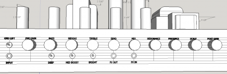
As for controls...
Knobs on the front:
- Pre Gain
- Bass
- Mid
- Treble
- FX Send Level
- Dry/Wet Signal Mix
- Reverb
- Resonance
- Presence
- Post Gain
Knobs on the back:
- Scale control (a pot in series with the PI cathode to bias it closer to cutoff)
- Feedback amount
Switches on the front:
- Ground Lift
- Deep Boost
- Mid Boost
- Treble Boost
Switches on the back:
- 8/4 ohm output
Looking now, I accidentally put the Scale control on the front instead of Reverb in the model. Whoops.
Attachments
You're confident that running the 3.45A @6.3V heater current in my amp off of a winding rated for 3.15A @6.5V is a bad idea? I could really use the extra space on the chassis without the 12.6V transformer to position the tubes better, and find room for a reverb tank.
The way that I'm thinking about this, one of two things will happen. I'm using far less current than the transformer is rated for on the B+ winding, and slightly more than it's rated for on the 6.5V filament winding. The VA rating of the transformer far exceeds my full signal demands. So either the transformer will run hot and potentially be damaged over time and introduce extra noise because I'm drawing more current than the winding is rated for, or the slightly higher voltage (6.5V) will get pulled down to around the 6.3V that I need because of the winding resistance, and it won't be much extra work for the transformer because it's rated overall much higher than what I need. It would be a gamble, and I'm not sure what to expect because this is my first build.
Also, since all of my controls are on the front, I might look at moving the tubes to the back so I can keep my heater wiring away from the signal.
Last edited:
 Seems like this really would work much better for you if this thread was in the guitar amp forum which is otherwise known as Instruments and Amps. I'm moving it.
 Agreed, my amp is around 40W. Is your power scaling just a potentiometer in series with the PI cathode, to put it closer to cut-off?
No, It is done by using a MOSFET to adjust the CT of the primary of the OT to lower the voltage. Also lowering the -ve control grid voltage proportionally. This is as if the amp is operating at lower and lower voltage. The B+ of the rest of the amp is constant.
This power scaling is how I started my career in electronics in 1978. At the time, I did not know much electronics, I just notice when I shipped my Marshall Plexi over from Hong Kong, when I forgot to change the setting from 220V to 110V, the amp sounded soft and distorted. So I started in working on how to cut down the power. I finally use a separate filament transformer to power the filament, string quite a few of the tiny 36V transformers together to get about 300V to power all the preamp tubes. Then I use a small variac borrowed from the Chemistry lab in school to vary the voltage of the PT, WOW was it nice sounding. I made my Twin into a delux, a Bronco or a Champ just by turning the variac!!!
I did not pursue it any further, In fact I quit music since 1980. I did not pick it up until lately after I retired. But now others have come up with the idea also, using MOSFET.
If you are interested, do a search of London Power, they sell the kit and they have paper explaining this. It really works, better than using attenuators or master volume, they are not in the same league. I have the THD Hot Plate to compare, no comparison.
You're confident that running the 3.45A @6.3V heater current in my amp off of a winding rated for 3.15A @6.5V is a bad idea? I could really use the extra space on the chassis without the 12.6V transformer to position the tubes better, and find room for a reverb tank.
No I don't know. But transformer is very forgiving particular if you are not using all the B+ current capability.
I am not going to suggest you to use under rated component, it's up to you to take the chance. Monitor the temperature, if it does not get too hot, then it should be ok.
Last edited:
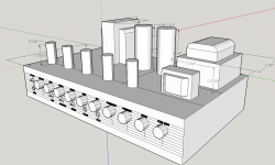
An idea what this might look like when done.
I want to put a MOD 8EB2C1B reverb tank inside the chassis, though, so I may need to go up another inch or two in width and move parts around.
Don't put the reverb tank inside the chassis. It will pick up all sorts of hum and other noise. I have never seen a reverb tank inside an amp chassis and for good reason. You should even keep it away from the chassis when mounting outside of the chassis especially from any transformer. Notice how most combo amps have it down on the bottom of the cab?
Don't put the reverb tank inside the chassis. It will pick up all sorts of hum and other noise. I have never seen a reverb tank inside an amp chassis and for good reason. You should even keep it away from the chassis when mounting outside of the chassis especially from any transformer. Notice how most combo amps have it down on the bottom of the cab?
I've seen a few of them inside the chassis, but mostly on solid state amps.
http://www.thegearpage.net/board/in...on-the-amplifiers-chassis-is-that-ok.1420604/
With the transformers mounted on the outside and opposite end of the chassis, the shielding around the reverb tank wouldn't be enough to block the interference?
You build your amp from ground scratch? I don't. I am not that good in carpentry and metal work. I used a cheap KMD 1X12 for my first amp. I ripped off everything and just use the chassis. I put in PT, OT, drill my own holes for tubes, just using the chassis and cabinet.
I use my old Marshall JCM900 Dual Reverb 1X12 as the platform of my second amp. It's about the lousiest sounding high gain amp I tested. I was stupid to buy that one long time ago. BUT the chassis is very thick and strong. So again, I ripped everything out and started from scratch. I even braced up the cabinet( that turn out to really improved the sound!!! ) as Marshall use very thin wood for cabinet. I totally got rid of the boxy sound.
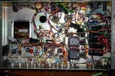
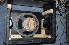
Attached are two pictures of my last build. I quit guitar amp after this and moved into audiophile here.
Notice the two heat sink, those are the MOSFETs for power scaling.
I use my old Marshall JCM900 Dual Reverb 1X12 as the platform of my second amp. It's about the lousiest sounding high gain amp I tested. I was stupid to buy that one long time ago. BUT the chassis is very thick and strong. So again, I ripped everything out and started from scratch. I even braced up the cabinet( that turn out to really improved the sound!!! ) as Marshall use very thin wood for cabinet. I totally got rid of the boxy sound.
Attached are two pictures of my last build. I quit guitar amp after this and moved into audiophile here.
Notice the two heat sink, those are the MOSFETs for power scaling.
Attachments
I've seen a few of them inside the chassis, but mostly on solid state amps.
Mounting a spring reverb tank on the amplifier's chassis - Is that ok? | The Gear Page
With the transformers mounted on the outside and opposite end of the chassis, the shielding around the reverb tank wouldn't be enough to block the interference?
don't put it inside, it's tight enough inside already. Layout is critical. I can tell you, I first experiment my circuit in my Bassman 100 chassis. Because it's a working progress, adding stages, changing filters and all, components are not optimized and a lot of crossing. It always sound a little funny even though I get the distortion effect I want. Then I design the layout into the new chassis to build the amp. Because I don't have to experiment, I optimize the layout and put build it. It sounds better, more open up. the same circuit sounds different and better with an optimized layout.
So, optimize the layout, battle is won or lost on the layout. Don't complicate the layout and placement with a huge reverb tank inside.
Don't laugh at my layout in the picture, it looks messy, but this layout is done using high speed point to point technique to eliminate as much crosstalk and ground loop as much as possible. It is dead quiet and work one time through. If you look at the very high end tube amp called Cary, their gut shot does not look any better.
Last edited:
Is there a reason you want it inside the chassis? Higher voltage amps have larger magnetic fields surrounding the circuitry. In SS amps the voltage isn't as high. The link you gave does show some, the Frontman 25 has a tank 1/2 the size, they gave any old Silvertone as an example but the four I have are on top of the chassis or in the combo, it's on the bottom where almost all amp builders have it. And those are cheap single spring designs anyway. I suppose keeping it down by the preamp end and shielding it would be your best bet.
You need a cab anyway, why not mount it on the inside top where many amps have them away form the power tranny. And just because some amps have it inside doesn't mean it is quiet. I saw some old amps in that thread and back then there was a lot more to learn about amps.
Or if it is a combo, why not on the bottom? There seems to be more obstacles to overcome with it inside.
- Status
- This old topic is closed. If you want to reopen this topic, contact a moderator using the "Report Post" button.
- Home
- Live Sound
- Instruments and Amps
- Guitar Tube Amp - Double Checking Choice of Power Transformer