Point taken, I was also thinking the comments from Ostripper and others that they feel the sound open up on higher rail voltages. That I have to lower the bias current and raise the Re to meet Oliver's condition. Is there any truth about higher rail voltage give better sound? If so, why?
I read p300 and 301 many times, you specifically said this is for a single transistor. If you look at equation 15.2, the gm calculation is for single transistor and so is the thermal resistance 1.1deg/W is for a single transistor. So I assume you meant this is the worst case in hogging that one transistor hog up all the current. That if the parallel transistors are sharing current, it is going to be a lot more forgiving.
Thanks
Higher rail voltage will give better sound because the amplifier will clip less because it has more power.
If you use 0.22 RE and bias to Oliver, a higher rail voltage should be no problem with the number of transistors you have as long as the heat sink is big enough to maintain a reasonable temperature.
If you have 8 pairs at 120mA each with RE=0.22, your total idle is about an amp. With 50V rails that is 100 watts idle dissipation. With 60V rails, that becomes about 120W idle dissipation. If you want to keep the idle heat sink temperature to 50C, that is a rise of about 25C over room, so the heat sink must have a thermal resistance of 25C/120 watts = about 0.2 C/w.
I'll really have to clarify that discussion about that equation and whether and if so how it applies to multi-pair output stages.
For the time being, recognize that the equation assumes an infinite heat sink. So the transistor being focused on really does not care about what the other transistors are doing. So if it has less thermal stability, it will more likely be inclined to increase its bias level, so that would seem to translate to a higher probability that it will hog current if it is, say, the one with higher beta. Note also that beta goes up with temperature, which further exacerbates things.
Cheers,
Bob
Hi MiiB,
Once you have matched and thermally coupled your differential pair, you do not want to unbalance it. The main job of the diff. pair is distortion subtraction. If you unbalance it for fear of some offset of, say 30 mV, you are destroying the audio performance for fear of some meaningless DC offset. In truth, the DC offset could be handled later in the circuit - like the Vas stage, or in the driver stage depending on how you designed it. You want the diff. pair to deal with the audio portion.
Most amplifier designs will have less than 50 mV DC offset, and that is in no way harmful to the speaker. If the design is so poor that you do have DC offset in the hundreds of mV, I respectfully suggest that you fix the problems in the design (or execution) instead of throwing a DC servo in there to handle the problem. What I just said is that a DC servo isn't required for most designs, but it does eliminate a "click" out the speakers when the relay closes. Hopefully a very small "click" sound.
One design that might be worthwhile looking at is the old BGW 750C amplifier. They had adjustable emitter resistance in the driver stage. The idea was to adjust the driver current against the other polarity (which ever one required a change) while monitoring the DC voltage on the output of an LM318 Op Amp that was used as the front end. I think their limit was on the order of +/- 100 mV on the output of the LM318. The actual DC offset on the amplifier wouldn't change much, if at all due to the action of the LM318 correcting this. By bringing the DC offset of the LM318 down to <100 mV, you were balancing the entire amplifier so it's natural tendency would be to be balanced. This left the LM318 to handle the audio to subtract and invert the distortion component. Cleaner sound.
Look at this another way. If you just went through a ton of work to match some input devices, then secured them together mechanically, why on earth would it make sense to unbalance that arrangement? That is exactly what 99% of the DC servos do out there. BTW, it isn't that DC servos sound bad (to some), it's the way they are made to work and the affect they have on a balanced input stage. Isn't that funny?
-Chris
I normally don't quote entire messages, but this was a page ago.Anatech, why is unbalancing not the way to deal with DC.?? as I see it, altering the currents shifts the device to a different working condition, where you have an exact gain matching in the two symetric halves. I normally make my houskeeping by feeding the circuit through current mirrors, then I can servo shift the currents by injecting different currents up/down. (Normally the driving currents are very close of each other (uV) as the DC gain is high)
Once you have matched and thermally coupled your differential pair, you do not want to unbalance it. The main job of the diff. pair is distortion subtraction. If you unbalance it for fear of some offset of, say 30 mV, you are destroying the audio performance for fear of some meaningless DC offset. In truth, the DC offset could be handled later in the circuit - like the Vas stage, or in the driver stage depending on how you designed it. You want the diff. pair to deal with the audio portion.
Most amplifier designs will have less than 50 mV DC offset, and that is in no way harmful to the speaker. If the design is so poor that you do have DC offset in the hundreds of mV, I respectfully suggest that you fix the problems in the design (or execution) instead of throwing a DC servo in there to handle the problem. What I just said is that a DC servo isn't required for most designs, but it does eliminate a "click" out the speakers when the relay closes. Hopefully a very small "click" sound.
One design that might be worthwhile looking at is the old BGW 750C amplifier. They had adjustable emitter resistance in the driver stage. The idea was to adjust the driver current against the other polarity (which ever one required a change) while monitoring the DC voltage on the output of an LM318 Op Amp that was used as the front end. I think their limit was on the order of +/- 100 mV on the output of the LM318. The actual DC offset on the amplifier wouldn't change much, if at all due to the action of the LM318 correcting this. By bringing the DC offset of the LM318 down to <100 mV, you were balancing the entire amplifier so it's natural tendency would be to be balanced. This left the LM318 to handle the audio to subtract and invert the distortion component. Cleaner sound.
Look at this another way. If you just went through a ton of work to match some input devices, then secured them together mechanically, why on earth would it make sense to unbalance that arrangement? That is exactly what 99% of the DC servos do out there. BTW, it isn't that DC servos sound bad (to some), it's the way they are made to work and the affect they have on a balanced input stage. Isn't that funny?
-Chris
been sensing top of output transistors for over 30 yrs, also to-92 glued to collector lead, much faster than waiting for heatsink and since low power is in the path the thermal resistance does not develop much delta.
Good idea.
Sensing on the top of one output transistor, or with one ThermalTrak or pair, does certainly help with overall bias stability, as I showed in my Figure 14.23.
However, I'm pretty sure that these techniques do not mitigate current hogging among multiple output pairs. If this is true, then there remains significant concern in using RE = 0.1.
Cheers,
Bob
but a solenoid is a longer reaching inductive pickup than a bead so there's still a trade off - toroid air coil anyone?
It's the air toroid I had in mind.
Look at this another way. If you just went through a ton of work to match some input devices, then secured them together mechanically, why on earth would it make sense to unbalance that arrangement? That is exactly what 99% of the DC servos do out there. BTW, it isn't that DC servos sound bad (to some), it's the way they are made to work and the affect they have on a balanced input stage. Isn't that funny?
-Chris
Hey , Chris - we don't have matched 1381/3503's anymore. On a symmetrical
leach type amp , the 3503 is usually a "D" and the 1381 is a "E".
This messes things up a bit.
If it's a cascode VAS , I tell them to just pick a "stronger" BCxxx for the NPN side.
No cascode , pick higher gain NPN differential devices.
Doing that , before the servo is socketed - <30mv is typical. There is
a current source adjustment to get lower offset , but usually these
are adjusted in tandem for the global input pair(s) current.
This is my favorite present working amp (my leach - the "spook").
I've run with/ without the servo (It's socket-ed). @20mv without ,
+/- .1mv with. No difference in sound with or without.
Without the servo , I do trip the DC protect if I touch the board ...
much more sensitive ! I would not do this without protection - believe
me !
OS
Hi Pete,
I'm more into matching long tailed pairs and current source transistors. When it comes to complimentary pairs, you do the best you can and adjust elsewhere to compensate. Just don't adjust with the main diff pair, that's all.
At 30 mV, a servo isn't required at all. But, it would be interesting is you could measure your THD with and without the servo.
In your case I would expect to see only a very, very small difference as the input pair is already unbalancing to deal with your DC offset. What you want is to see if you can balance the circuit elsewhere that brings the diff pair more into balance. Looking at the Vb of each transistor (tricky, easy to induce a charge there) to see if they are equal. If your base voltages are equal and the pairs are well matched, then the rest of the amp is balanced as far as the diff pair is concerned. Remember, you want the diff pair to deal with the audio only, and the servo should deal with the DC offset voltages.
To measure the "unbalance" of your diff pair, you would have to have equipment connected before you power up the amplifier without injecting noise from the meter. The less expensive meters can inject quite a buzz (the sampling rate of the input voltage). If there is a different, less sensitive place to find balance, that would be better. Between the collectors maybe? I am not looking at your schematic at the moment.
Anyway, interesting test that I should do some day - after the new bench is in place! I have a differential probe that might make this an easy test. All I need then is an amp that I can connect and disconnect the DC servo from without driving the poor amp nuts! You know, a front end that was capacitive coupled past the Vas, like a hybrid tube amp but solid state, that would isolate the diff pair from the DC offset stuff. The driver-output stage would have it's own servo for DC offset. Interesting thought.
-Chris
By top sensor, Do you mean the bias spreader transistor is BOLTED on top of the power transistor?
QUOTE]
Clamped, usually, but basically yes.
Hi Doug,
Yes, I've always thought the idea of putting the sensing transistor on top of one of the power transistors was a good idea, and it makes sense that this would help. I'll add a discussion of that in my second edition and give you due credit. Is there anyone else that I should also credit in that regard?
Not that I know of, but see the later discussion.
Sort of half way between using the heat sink and using a ThermalTrak.
Absolutely not. The ThermalTrak diode basically measures the heat sink temp.
BTW, have heard rumours that ThermalTraks are going to be discontinued. Anyone know anything?
Thanks for the reply. Needing the head room is another ball game exactly opposite to having a large Class A. The static power dissipation is going to be a big problem.Higher rail voltage will give better sound because the amplifier will clip less because it has more power.
If you use 0.22 RE and bias to Oliver, a higher rail voltage should be no problem with the number of transistors you have as long as the heat sink is big enough to maintain a reasonable temperature.
If you have 8 pairs at 120mA each with RE=0.22, your total idle is about an amp. With 50V rails that is 100 watts idle dissipation. With 60V rails, that becomes about 120W idle dissipation. If you want to keep the idle heat sink temperature to 50C, that is a rise of about 25C over room, so the heat sink must have a thermal resistance of 25C/120 watts = about 0.2 C/w.
What is your opinion on on the sound comparing between bigger class A region but lower rail vs lower bias and higher rail voltage to avoid clipping? Ostripper actually bias below Oliver's condition and only have about 12mV across Re to keep the dissipation down to use high rail voltage.
If you were to design an amp, what rail voltage, Re and bias current would you use?
Heat dissipation is actually the biggest problem for me. I already paid $280 for the chassis, the heat sink is 12" X 5.75" X 2" already. From people that know the chassis here, it can only keep up with 70W static dissipation max. Any bigger chassis will be in $500 range!!
If high rail voltage is important, I might even have the wrong transformer. I bought the 30-30 625VA to get 40V for bigger class A region. If I turn around to higher rail and lower current, I might need to buy a new transformer.....like a 35-35 to get 50V rail or even higher.
Thanks
Last edited:
Loss is not the issue , speed is. Metal is quicker than epoxy - period.
OS
I am comparing to the way I do it, which is bolting the KSC3503 on top of the MJW with a single screw. Of cause with heatsink compound in between.
A.The ThermalTrak diode basically measures the heat sink temp.
B. BTW, have heard rumours that ThermalTraks are going to be discontinued. Anyone know anything?
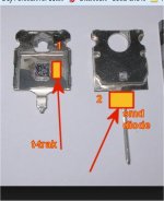
A. measures the slug temp. that would be much faster because of distance
(below - #1) and not having the insulator/heatsink thermal resistance.
(below # 2) is the "Bonsai technique". A SMD diode on the PCB lowered
onto the collector pins . Slighty more distance . That "best' HK990
sensor design would most likely be nearly perfect with this implementation.
Through plastic or the extrusion , you could never get fast responses.
ON's marketing - "eliminate thermal equilibrium lag time" and
"Superior Sound Quality Through Improved Dynamic Temperature response" ..
The former is a lie , it just reduces it. The latter my be true compared to the output
stage that only has the sensor on the heatsink or plastic.
B .The NJL3281D is dead (obsolete). They have the "G" version to-264.
NJL3281G = active/final.
Even if they do discontinue , just add the two SMD pads to any T-trak PCB design -
find a diode with similar Tc - futureproof !
OS
Attachments
I am comparing to the way I do it, which is bolting the KSC3503 on top of the MJW with a single screw. Of cause with heatsink compound in between.
You get more loss through the plastic. There is no way around the plastic
vs copper thermal resistance comparison.
3503 ? I've tried BD139 /3503 / and the 340.
They all had different Tc's. The 340 is the best , BD and 3503 , I would
end up too much NTC >50C. Sensor don't need to be high Ft , it's just a decoupled shunt.
OS
I place a piece of 3mm copper between the transistors and heat sink, that evens out temperature nicely. My VBe is placed in the middle.
Not so sure about a fast Temprature compensation it should be an adjustment for thermal tendencies and drift. Current hogging should be dealt with by other means, beta matching and Re.
Somehow I like the idea of using an air coil parallel with a resistor for base stoppers.
Not so sure about a fast Temprature compensation it should be an adjustment for thermal tendencies and drift. Current hogging should be dealt with by other means, beta matching and Re.
Somehow I like the idea of using an air coil parallel with a resistor for base stoppers.
Last edited:
Hi MiiB,
I normally don't quote entire messages, but this was a page ago.
Once you have matched and thermally coupled your differential pair, you do not want to unbalance it. The main job of the diff. pair is distortion subtraction. If you unbalance it for fear of some offset of, say 30 mV, you are destroying the audio performance for fear of some meaningless DC offset. In truth, the DC offset could be handled later in the circuit - like the Vas stage, or in the driver stage depending on how you designed it. You want the diff. pair to deal with the audio portion.
Most amplifier designs will have less than 50 mV DC offset, and that is in no way harmful to the speaker. If the design is so poor that you do have DC offset in the hundreds of mV, I respectfully suggest that you fix the problems in the design (or execution) instead of throwing a DC servo in there to handle the problem. What I just said is that a DC servo isn't required for most designs, but it does eliminate a "click" out the speakers when the relay closes. Hopefully a very small "click" sound.
One design that might be worthwhile looking at is the old BGW 750C amplifier. They had adjustable emitter resistance in the driver stage. The idea was to adjust the driver current against the other polarity (which ever one required a change) while monitoring the DC voltage on the output of an LM318 Op Amp that was used as the front end. I think their limit was on the order of +/- 100 mV on the output of the LM318. The actual DC offset on the amplifier wouldn't change much, if at all due to the action of the LM318 correcting this. By bringing the DC offset of the LM318 down to <100 mV, you were balancing the entire amplifier so it's natural tendency would be to be balanced. This left the LM318 to handle the audio to subtract and invert the distortion component. Cleaner sound.
Look at this another way. If you just went through a ton of work to match some input devices, then secured them together mechanically, why on earth would it make sense to unbalance that arrangement? That is exactly what 99% of the DC servos do out there. BTW, it isn't that DC servos sound bad (to some), it's the way they are made to work and the affect they have on a balanced input stage. Isn't that funny?
-Chris
Hi Chris,
Most DC servos I have seen, including my own, do not unbalance the LTP. They feed a DC correction voltage back to the input of the LTP where the feedback network goes. This does not unbalance the LTP. Note that IPS that use a current mirror will have their balance enforced by the current mirror.
The DC servo eliminates the crappy electrolytic normally used in the feedback network to reduce gain to unity at DC.
Cheers,
Bob
Not that I know of, but see the later discussion.
Absolutely not. The ThermalTrak diode basically measures the heat sink temp.
BTW, have heard rumours that ThermalTraks are going to be discontinued. Anyone know anything?
Doug,
With all due respect, you are completely wrong. It is well-explained in my book. The ThermalTrak diode responds to the temperature of the common header that the transistor itself is attached to. This is NOT the same as the heat sink temperature at all. The temperature sensed by the ThermalTrak diode includes most of the junction temperature rise above the heat sink temperature, and responds much more quickly. It is thermally "closer" to the power transistor junction than the junction of a bias spreader transistor mounted to the package of the power transistor.
Cheers,
Bob
Regarding location of the bias spreader, please see my earlier posts (#5606 & #5624) regarding placement of the spreader device atop the power device. If you surround the entire arrangement in insulating foam, the tracking will be very good. Tracking is still superior to mounting on the heatsink or heat-spreader bar, even without foam.
Regarding current hogging, I am failing to see how the bias spreader can help here, if you only have one bias spread device. If the bias spreader is not mounted on top of the device that starts to hog current, surely this will in fact make things worse? The device that isn’t hogging will run cooler, so the bias spreader will cool and the bias will go up. The hogging device will then take proportionately more of this increased bias current, get hotter and hog more.
Regarding current hogging, I am failing to see how the bias spreader can help here, if you only have one bias spread device. If the bias spreader is not mounted on top of the device that starts to hog current, surely this will in fact make things worse? The device that isn’t hogging will run cooler, so the bias spreader will cool and the bias will go up. The hogging device will then take proportionately more of this increased bias current, get hotter and hog more.
Absolutely not. The ThermalTrak diode basically measures the heat sink temp.
I don't think this is correct. The ThermalTrack diode is a separate chip, but it is placed on the same collector substrate as the power chip. The thermal impedance between the diode and the power silicon chip is much lower than the thermal impedance between the diode and the heatsink.
You can easily verify this (I did) by pulsing the ThermalTrack power device and measuring the diode response (direct bias voltage). If the power pulses are apart (say) 10 seconds or so, you can see the diode response following, while the heat sink remains pretty much at room temperature all along.
Regarding current hogging, I am failing to see how the bias spreader can help here, if you only have one bias spread device.
Neither do I. I am placing the "blame" on Mr. Cordell which IMO did not treat these things clear enough in his book, hence the widespread confusion among newbies as Alan.
The confusion is between thermal runaway, which can indeed be caused by a (too) small heat sink, (too) small emitter resistor (not enough feedback to stabilize), poor thermal impedances between the power device and the heat sink, etc...
Current hogging is crowding the current on one or more of the paralleled devices. While certainly the factors affecting the thermal runaway are playing a role as well, I think it is the thermal gradient on the heat sink that is mostly responsible, and this is related to the bias spreader and thermal compensation positioning. Consider a pathological bad layout in which the bias spreader is thermally coupled to one of the outer transistors. This would create a situation in which the transistors in the middle of the heat sink would, in time, carry most of the current (being hotter). If the heat sink is large enough, it could be that until the heat reaches the bias spreader, the middle transistor already exceeedede the SOA and kaboom... Otherwise said, the best method to avoid current hogging are 1) matching devices (so that beta is within reasonable limits, 1% as mentioned here is plain stupid to look for) and 2) making as much as possible the temperature constant across the heat sink. And making the thermal impedances between the heat sink and each device as much as possible uniform (same pads, same torque, etc...).
I'm thinking that a micro controller (they come with up to 16 A/D and D/A channels) would be very effective controlling the bias of each power device pair, so that everything stays nicely balanced. The same micro controller could also provide a way to avoid thermal distortions (since they can adjust so much faster than the audio signal) Much to complicated though, for a poor amplifier that, if correctly designed, could satisfy the most picky audiophiles (if they don't peek, of course) anyway...
Last edited:
- Home
- Amplifiers
- Solid State
- Bob Cordell's Power amplifier book