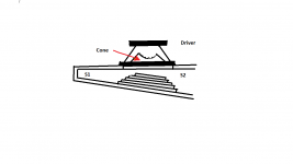
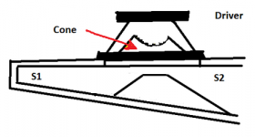
This is a follow-on to my test case showing the impact of using "cone compensation", which is basically accounting for the volume of air contained within the driver's cone when designing the layout of a TH. The end result of using cone compensation was partial filling in of some of the dips just outside the passband of the TH in question (my POC3), a result that was predicted by the corresponding HornResp sim.
But what if we go a bit further and actually pinch in the CSA at S2 significantly more than may be required by cone compensation?
The results of a HornResp sim using a "single-expansion" TH suggest that pinching in a TH at S2 may result in further filling in of the notches in the FR that can be found just outside of a TH's passband, and of course this can also result in a decrease in overall cabinet volume if it is incorporated into the layout of the TH.
Unfortunately in HornResp you have to use S1 to S3 to emulate the pinch, which limits it to emulating only single-expansion THs with such a pinch. But the results do give a fairly decent idea of what to expect if you deploy such pinches with other TH layouts.
So, I've decided to try it out with my POC3. I'm going to start by pinching in S2 by 6 liters, basically double the volume I estimated that I would need for cone compensation.
Method and results will be posted in followup messages...
Attachments
S2 Restriction - a test case: method
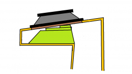
I wanted to have a little flexibility with this test (i.e. the ability to add or remove to the restriction as needed), so I plan to implement it by screwing together a few layers of ply of different sizes, one on top the other. Adding or removing volume will then be as simple as adding or removing the appropriate number of layers. To help with the process, I designed a spreadsheet that would basically take a few input parameters, like the target volume, the panel thickness, the maximum width, the height at S2 and the slope of the driver's cone, and spit out the required dimensions for each panel. See example output below.
It's a bit too dark here now to start cutting wood, so start work on cutting the panels tomorrow.
Attachments
Are you planning to use round filler pieces or horizontal pieces. Or both for testing the differences.
Just horizontal pieces. At the frequencies being discussed here, rounding them over is likely to make no difference.
nope according to Brian, filler shapes are unimportant if they are under 1/4 wavelength of the upper bandwidth. IDK if he has convinced himself ,as he continues to use 'flowing type' profiles in there.Akabak would be very useful here for a more detailed profile of the S2 filler plug.
Last edited:
I wanted to have a little flexibility with this test (i.e. the ability to add or remove to the restriction as needed), so I plan to implement it by screwing together a few layers of ply of different sizes, one on top the other. Adding or removing volume will then be as simple as adding or removing the appropriate number of layers. .
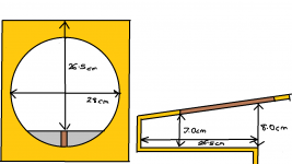
So, I've run into a little problem. See, knowing that my carpentry skills leave a lot to be desired, I decided to take a few measurements of the area to be modified before I rush off to cut any wood to create the restriction.
Good thing I did. It looks like I have a maximum length of 26.5 cm to work with, as there is a fold in the TH right after that. So, so much for starting off with a panel of length 31.1 cm - it's not going to fit in the box!
Secondly, if I do go with a panel of length 26.5 cm, it will have to be 21.5 cm or length or it's not going to fit in the box (it won't get past the driver's cutout in the baffle board.). The only way to get around this would be to cut the bottom panels into sections, and join them together in the box.
Finally, it looks like I have a maximum height of 7mm, not 9.5mm, to work with, before I have to start cutting down on the width of the panels, otherwise I run into the risk of the driver's cone hitting them on full excursion.
Grumble.
I'm going to need to come up with another means of getting that 6L restriction, before I start cutting any wood...

Attachments
nope according to Brian, filler shapes are unimportant if they are under 1/4 wavelength of the upper bandwidth. IDK if he has convinced himself ,as he continues to use 'flowing type' profiles in there.
LOL - good point. I do believe that, at the wavelengths being considered here, the shape is irrelevant, within reason of course (i.e. choosing a shape that significantly blocks off S2 is probably not going to give good results).
At 300 Hz, 1/4 wavelength is around 28 cm, which is basically the width of the driver cutout in my TH. The first big peak in my TH's response is at 160 Hz, where the wavelength is around 53 cm, which is double the length of the section in my TH where the restriction has to be inserted.
But this applies only to the impact on FR. As for other things, like aiming for even pressure across the cone, for example, it may not apply. I don't have the means to measure things like that however.
@ Brian Steele
Experimenting is always welcome, & can & has led to some useful developments
I've tinkered around with S2 type restrictions before, & noticed some interesting results.
I have a feeling, that the shape/size of the CC block might be more critical than some may think. Have a look @ my screenie for one such suggestion.
Attachments
I have a feeling, that the shape/size of the CC block might be more critical than some may think. Have a look @ my screenie for one such suggestion.
Unfortunately that won't work because of the physical layout of the TH I'm using for the test. There is a bend in the layout, a few cm before the edge of the driver's cutout.
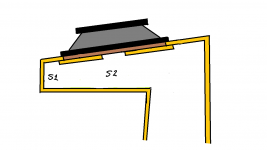
Here's the approach I'm considering at the moment. Unfortunately I don't think I'm going to hit my target of 6L with it. I may have to settle for something smaller, like 4.5L.
Attachments
Brian, I fail to see how you are testing anything other than increased compression ratio with this experiment. increasing compression ratio "fills in" the dips at the upper end of a tapped horns response. that appears to be what you are expecting to happen.
Well, I am hoping to fill in the dip in response around 130 Hz
.I think this goes a bit further than compression though. For example, the attached shows a method of increasing compression at the driver, but there's little or no volume change @S2.
Attachments
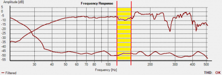
Well, I am hoping to fill in the dip in response around 130 Hz
I've highlighted the section in particular I'm trying to address.
In my "cone compensation" exercise, I was able to lift the response in this area by between 2~3dB by adding a 3L "wedge" at S2. I'm hoping a larger wedge will lift it even further. With the CC mod the TH has a response that's within a +/- 3dB window from 42 Hz all the way up to 150 Hz, but I guess the results of the CC experiment have made me a bit greedy
.Attachments
@ Brian Steele
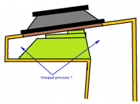
I see. My concern is the possible unequal loading/pressure etc between each half of the cone, & what difference it might make ?
Hm.... I suspect the loading on each side of the cone is going to be different anyway, as one side leads on to the rest of the TH, and the other does not. How does one go about equalizing that situation?
hey brian. in simulation we can see that adjusting ap1 does not fill in the dip, but simply dragging the s2 slider down (and to some degree, the s1 slider) does indeed fill in the dip.
Yeah, they both seem to have different impacts on the FR, though decreasing Atc is a way of increasing compression in front of the driver that's been suggested here before, and it's also visible in a number of commercial builds (like the CV EL36, for example). A little experimenting in HornResp suggests that for my particular TH, I can decrease Atc to almost 1/3rd of Sd before changes to the FR in the passband start to become noticeable. Above that, some dips start to get filled in, while others get deeper.
Originally Posted by Brian Steele
How does one go about equalizing that situation?
Well, exactly, how ? Not sure right now, but i'll give it some thought
OK, now you guys touched on something I've always wondered about. Seems like all the DIY TH do not take into account both side of the cone... Never understood that but most of this is beyond me. To me, it's logical to think restricting the cone side farthest from S1 will force this energy toward S1. In my mind this alone should gain us some SPL. This nixes the CC idea tho. Now, if restriction is welcome, then I would also wonder if there is some advanced folding/3d folds nearest driver that would also gain us path length. Cheesy pic but some good related discussion: http://www.diyaudio.com/forums/subw...tapped-horn-design-concept-6.html#post4280394
Each cab is different and I suspect good designers like DSL will apply the best S1 mod/technique for each cab, some may not even need it, like big SOBs. But I am sure there are standard recipes but each is seasoned to taste... Fill notches/lower Fb/higher SPL.
If I had time and room to test, I would to test varying restrictive/compensation ideas with a simple single fold cab with a removable side, kinda like Art did with the KS.
- Status
- This old topic is closed. If you want to reopen this topic, contact a moderator using the "Report Post" button.
- Home
- Loudspeakers
- Subwoofers
- S2 Restriction - a test case