-2mV/deg of Vbe, so the hotter it gets, the lower the Vbe and more voltage drop across Re that cause more current, then it get's hotter, draw more current until it burns.
this is true whether you use Re=0.5 and run 50mA or 0.12 running 200mA. It should be all about the heatsink capability and rail voltage. Am I missing something?
Yes. It is, in the 1st, 2nd, 3rd etc case, not about heatsink and rail voltage. The Re provides local feedback, in the sense that the larger the Vre, the smaller the proportion of Vbe on the total voltage resulting from the current, and the smaller the effect of the heating. So, the larger Re, the less hogging, and less change that one pair takes all and blows. This is of course all a continuum - no yes/no thing.
Feedback is sooo nice ;-)
Jan
Last edited:
Oliver's condition essentially takes the average error over the whole transfer curve and finds the degeneration voltage which gives an overall good result. If you exclude the class B region, then optimizing only the class A region results in a different optimal degeneration value.
This is quiet easy to see when you adjust bias via distortion analyzer. Should show up in SIM as well.
THx-RNMarsh
Why not make something non switching, Then you never leave class A region, even with a low bias of 60mA and 0,47 ohm Re.
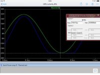
Here voltage output and associated Ops current into 4ohm load.
One single set output transistors biased heavily into class A driving 8 pair Oliver biased dumpers creates a Non switching OPS (Dumpers spread with resistors to output)
The idea is that when the load demands more current, then the drivers will dalso eliver more current in balance withe the biased dumpers and thus keep them away from switching. In my setup switching only happens when the output is forced very close to the rail, and then also with the gradual turn off/on seen here
Attachments
Last edited:
-2mV/deg of Vbe, so the hotter it gets, the lower the Vbe and more voltage drop across Re that cause more current, then it get's hotter, draw more current until it burns.
this is true whether you use Re=0.5 and run 50mA or 0.12 running 200mA. It should be all about the heatsink capability and rail voltage. Am I missing something?
That's too simplistic. You just describe thermal runaway.
It's how multiple pairs will respond to a thermal cycle. The Vbe keeps
the whole from running away , but at >50C ... does one pair (or device)
"hog" current from it's "group" (2 or more devices).
Good thermal conductivity between devices and matching will reduce this.
Higher Re will , as well.
I have one unmatched amp in front of me now - at 25C - 3mV difference.
When things heat up to 40C+ , less than 1.5mv between devices (.22R).
Sheet plots are B-E Tc vs. Ic , but no B-E versus C (0-50C).
OS
Note that if you want to run deeply into class AB and incur gm doubling, you can use modest error correction to pretty much wipe out the distortion from the gm doubling and get less overall distortion anyway. The HEC error correction circuit can be relatively easily implemented with about 4 extra small-signal transistors, and probably ends up being no more complex than a class XD-PP arrangement.
Cheers,
Bob
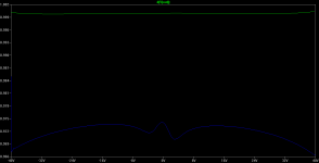
here is the plot of the derivative of V(out) versus V(in) for bipolar buffer amp with hec, http://www.diyaudio.com/forums/soli...ur-solid-state-pics-here-418.html#post4388005
green trace - hec on
blue trace - hec off
Attachments
I actually don't find releasing the magic smoke all that educational
building something you don't know/expect to work only helps if the circuit lives, works enough to be probed, exercised
if it just blows up then you have a very expensive 1 binary bit of information
Light bulbs, variac, current limiting, fuses etc.
Yes. It is, in the 1st, 2nd, 3rd etc case, not about heatsink and rail voltage. The Re provides local feedback, in the sense that the larger the Vre, the smaller the proportion of Vbe on the total voltage resulting from the current, and the smaller the effect of the heating. So, the larger Re, the less hogging, and less change that one pair takes all and blows. This is of course all a continuum - no yes/no thing.
Feedback is sooo nice ;-)
Jan
One thing you have to realize, I am always go for Oliver's condition. No matter what resistor value, I tune the bias so I get 26mV across the Re. I think everyone keep assuming I don't adjust the bias to Oliver's condition, that using a larger resistor result more voltage drop across the Re and buffer out the the Vbe variation. This has never been true in my case from day one.
It really does not matter what resistor value, I get 26mV across. It is no more forgiving to use a 0.47ohm vs 0.12ohm as long as you have the capability of removing the heat. That's why I said it boils down to ability of heat dissipation and how much margin of the power transistor. I have a pretty nice chassis that is good for 60W heat dissipation. I use 5 stages of TO-264 200W MJW3281/1302. No matter how you derate the transistor, I can handle a lot of power.
I also willing to stay with 30V rail to lower the dissipation. I am willing to sacrifice max power to get the wider Class A region. I think you have to take all these into consideration.
That's too simplistic. You just describe thermal runaway.
But isn't this the ONLY concern here?
As I described in the last post, I use a nice chassis with large heatsink, 5 pairs of MJW1302/3281 TO-264 200W transistors. I am even willing to run 30V rail or even lower if I have to in order to keep the Re=0.12 and run 200mA so I get 8W of Class A.
I am conforming to Oliver's condition no matter what. I will not have more voltage drop across the Re. It's only going to be 26mV across the Re no matter what value Re I use. So increasing to 0.47 does not make it safer. To me, it's all about the power dissipation. What I have done everything to lower........Low rail, 5 stages of 200W transistor, chassis that cost me $280.
Tell me whether I miss anything.
Thanks
One thing you have to realize, I am always go for Oliver's condition. No matter what resistor value, I tune the bias so I get 26mV across the Re. I think everyone keep assuming I don't adjust the bias to Oliver's condition, that using a larger resistor result more voltage drop across the Re and buffer out the the Vbe variation. .
The stabilizing local feedback from the Re has nothing to do with the actual set voltage across it. Think about how this feedback would work and the pieces will fall into place.
Edit: assume one pair with 0.1 ohm Re. Assume that due to heatsink asymmetry, or asymmetric mounting, or unequal cooling, one B-E is 5 degrees hotter than the other. Calculate he difference in current between the two and the resulting difference in dissipation.
Now do the same with 0.47 ohms Re. Eureka! ;-)
Jan
Last edited:
Agreed, with the accuracy of modern circuit simulators there isn't a lot of merit in trying a circuit in real life that a circuit simulator shows will obviously not work.I actually don't find releasing the magic smoke all that educational
building something you don't know/expect to work only helps if the circuit lives, works enough to be probed, exercised
if it just blows up then you have a very expensive 1 binary bit of information
But isn't this the ONLY concern here?
As I described in the last post, I use a nice chassis with large heatsink, 5 pairs of MJW1302/3281 TO-264 200W transistors. I am even willing to run 30V rail or even lower if I have to in order to keep the Re=0.12 and run 200mA so I get 8W of Class A.
I am conforming to Oliver's condition no matter what. I will not have more voltage drop across the Re. It's only going to be 26mV across the Re no matter what value Re I use.To me, it's all about the power dissipation. What I have done everything to lower........Low rail, 5 stages of 200W transistor, chassis that cost me $280.So increasing to 0.47 does not make it safer.
Tell me whether I miss anything.
Thanks
I''l tell you the real story. I test everything at 40v rails before I finish.
Everything is much closer at those lower rails. B-E Tc vs. Ic seems to
be less of a factor <50V. When I go to my 73V rails is when one or
more of the devices will "hog" (not be consistent with the others).
I thought a larger Re would always facilitate better sharing ?So increasing to 0.47 does not make it safer.
I'm not "guessing" on any of this. I just put two output stages
in the freezer to get them 0C. Tested that , @ room temp (23C) ...
then went outside to the 35C+.
Monitored all 10 semi's through that to see what I had. I am
satisfied (will take the abuse).
")
OS
I''l tell you the real story. I test everything at 40v rails before I finish.
Everything is much closer at those lower rails. B-E Tc vs. Ic seems to
be less of a factor <50V. When I go to my 73V rails is when one or
more of the devices will "hog" (not be consistent with the others).
I thought a larger Re would always facilitate better sharing ?
I'm not "guessing" on any of this. I just put two output stages
in the freezer to get them 0C. Tested that , @ room temp (23C) ...
then went outside to the 35C+.
Monitored all 10 semi's through that to see what I had. I am
satisfied (will take the abuse).
OS
So I should be very safe if I run under 40V rail? I think you proof my point in that it all depends on the ability to dissipate the power of the heatsink. The higher the rail, the more power dissipated in each of the stages. Temperature rise more and more hogging, and more temperature rise.
I never have intention running over that. Actually I am using two 24V switchers for rail on my prototype test bed.
I am seriously thinking of getting a 22VAC-22VAC 500VA transformer to get 30V rail. With 200mA per stage and 0.12ohm, I get 8W class A for 4ohm, 16W for 8ohm load, Oliver's condition, 91W Class AB for 4 ohm and 45W for 8ohm. That's a lot of power. Dissipation at idle is 60W/channel.
I even consider a 15V-15V transformer to get 21V rail, Re=0.1ohm to get 18W class A power for both 4 and 8 ohm. 36W of Class AB for 4ohm. Dissipation at idle is 63W.
I think people see I use 5 stages and automatically assume I want to have 200W+ of power output and using 50V+ rail. I really want an amp that can provide Class A 99.9% and have the optimization to give 40 to 50W of Class AB power for the occasion jump in signal level in the program.
BTW, how do you test current hogging. Feeding a sine wave to the amp, amp drive a resistor load. Run at high output power?
Last edited:
I think maybe I should match the beta of the power transistors also. I did the Vbe matching to 1mV already, Vbe is not going to be an issue. I should put a 200ohm resistor from ground to the base, then draw 500mA through the transistor, then measure the voltage across the 200ohm resistor at the base to match the beta.
If I find 5 transistor that have match voltage drop across the 200ohm resistor, Then both the beta and Vbe are match and I can avoid hogging.
What do you think.
If I find 5 transistor that have match voltage drop across the 200ohm resistor, Then both the beta and Vbe are match and I can avoid hogging.
What do you think.
I would not give up my "effortless" 72V rail transient capability for anything.
I have "normal" 100W OEM amps (real good ones). Switch to the larger PS
5-pair with 1/2 kw peak capability - the music just comes alive.
Exceeding Xmax is my only issue now - need better speakers.
I notice you are judging your class A assumptions on an overbiased
OEM SQ experience.
I've overbiased a few OEM's , overbiased my DIY. Different OPS's
do not behave the same.
What you design and create will most likely be very different than
what came out of a factory. You might not need a wide
class A region on some designs for optimal performance and stellar
SQ.
OS
Tell me whether I miss anything.
dV/dI(I)
I would not give up my "effortless" 72V rail transient capability for anything.
I have "normal" 100W OEM amps (real good ones). Switch to the larger PS
5-pair with 1/2 kw peak capability - the music just comes alive.
I notice you are judging your class A assumptions on an overbiased
OEM SQ experience.
What you design and create will most likely be very different than
what came out of a factory. You might not need a wide
class A region on some designs for optimal performance and stellar
SQ.
OS
Ha ha, how loud do you listen to music?
What is SQ?
I have no experience, that's why I am confuse. I still have not received the 0.22ohm, and I don't want to just solder back the 0.12ohm. So I am just empty talk for the moment.
dV/dI(I)
Can you explain dV/dI? What is V and assuming I is the current through the transistor.
Hi
I hate to beat the dead horse over lowering the emitter resistor Re for output EF stage and increase bias current to satisfy Oliver's condition.
If you look at D Self's book p249 Fig 9.19. It is a 3 output stages in parallel. The Re=0.1 ohm that Self has been talking in p279. This is his Class B which is Oliver's condition. He uses 215mA bias current as described in Table 10.2 in p279. He obviously they it's safe to use as low as 0.1ohm Re and not worry about burning the amp!!!
My impression of Self's book is he does not go deep into theory, more like he did the experiment and publish the optimal result and you follow like in Table 10.2. Never explain about Oliver's condition, just give you the current setting for a particular Re. I take that he actually tested the circuit in Fig. 9.19 and deem it's safe.
I was told 0.1ohm only works for single output stage, that current hogging can occur when I have multiple output stages in parallel and risk burning the transistor. But Self did it and published in his book. Now I don't know what to think.
I would not use 0.1 ohm RE in ANY output stage - even a single. It is just my opinion, but I strongly disagree with Self even showing a 0.1 ohm RE example unless he accompanies it with well-grounded explanations about the dangers of doing it. Going down to 0.1 ohm just to get presumably lower distortion is just plain foolish, and is an example of sacrificing other amplifier characteristics for just a better distortion number.
I like low distortion and I like low noise, but I do not believe in sacrificing other amplifier characteristics just to achieve low numbers. Similarly, if you want lower HF distortion numbers by a factor of about 2, just increase the ULGF by an octave - you may get away with the reduced gain and phase margins, but it may not be wise.
I think Self explains the theory of where the 26mV magic number comes from, but I do not think that he gives the credit to Oliver.
Cheers,
Bob
- Home
- Amplifiers
- Solid State
- Bob Cordell's Power amplifier book