I got a loud noise in amp tda2003 amp.
When I connect the amp to a 12volt battery the noise in my speaker ca be barely heard.But when I connect it to an unregulated power supply (15volt transformer,rectifier,4700uF capacitor) I get a loud noise.
I did some experimenting -added an LM78.. regulator.At 18volts I get the noise.At 15volts the same.But at 12 volts the noise is gone.Maybe its volume is reduced enough not to be detectable by ear.
I tried to move cables around within the enclosure-power cables away for audio cables but nothing happens. I even took the transformer entirely out of the metal box .The result is that the noise get even louder.
I suspect a ground loop,a cold solder connection or even a bad component.I have no idea how to pinpoint the problem.Maybe its the tdas themselves.
What else can I try?
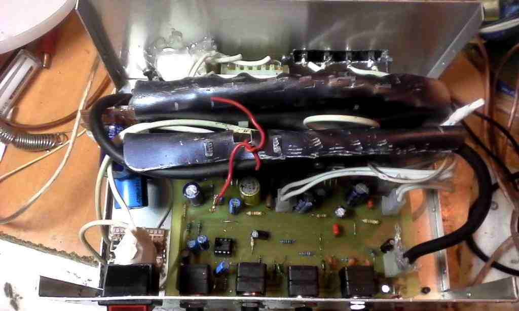
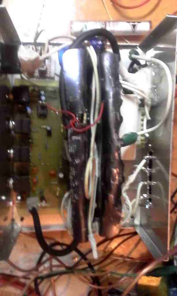
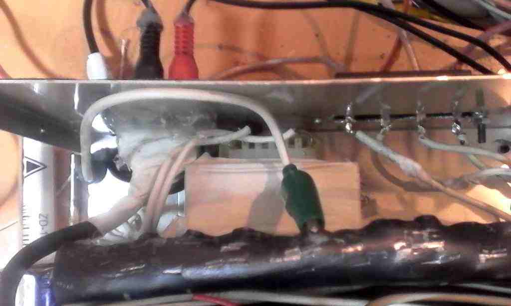
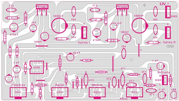
Here are the schematics and some pictures of the amp within the metal case.
As DIY as it gets! ????????????????: TDA2003 stereo amplifier with tone control 20 watts (10+10)
When I connect the amp to a 12volt battery the noise in my speaker ca be barely heard.But when I connect it to an unregulated power supply (15volt transformer,rectifier,4700uF capacitor) I get a loud noise.
I did some experimenting -added an LM78.. regulator.At 18volts I get the noise.At 15volts the same.But at 12 volts the noise is gone.Maybe its volume is reduced enough not to be detectable by ear.
I tried to move cables around within the enclosure-power cables away for audio cables but nothing happens. I even took the transformer entirely out of the metal box .The result is that the noise get even louder.
I suspect a ground loop,a cold solder connection or even a bad component.I have no idea how to pinpoint the problem.Maybe its the tdas themselves.
What else can I try?
Here are the schematics and some pictures of the amp within the metal case.
As DIY as it gets! ????????????????: TDA2003 stereo amplifier with tone control 20 watts (10+10)
Last edited:
It seems that your transformer secondary voltage may be too low for the regulator to work properly if the noise disappears at low voltage. What is the transformer's AC output voltage and VA rating?
How do you achieve 18, 15, 12V variations - with different transformer tappings or by using 7818, 7815, 7812 regulators for example?
You certainly could have noise due to wires going everywhere and possibly close to sensitive areas where they should not be but if you can reduce noise by lowering the power supply voltage, the major source of hum (or more likely buzz) would be the power supply itself.
Hi mitsof,
Well, at 12 VDC you will have about 4 watts into a 4 ohm load to play with. This chip will handle up to 28 VDC, so you should be pretty safe.
Your common ground routes may be the source of your problems. These can be very tricky to sort out. Each high current return, and your speaker returns must go to the filter capacitor directly. If your filter capacitor has long leads, it breaks all the rules immediately.
-Chris
It seems that your transformer secondary voltage may be too low for the regulator to work properly if the noise disappears at low voltage.
The noise is present but barely noticable even when powering the amp with a 12volt / 4Ah battery.
What is the transformer's AC output voltage and VA rating?
How do you achieve 18, 15, 12V variations - with different transformer tappings or by using 7818, 7815, 7812 regulators for example?
The AC ouput is 15 volts and it can put out up to 2 amps.By using different regulators-7818,7815,7812.
You certainly could have noise due to wires going everywhere and possibly close to sensitive areas where they should not be ...
I moved around the wires-nothing happens.I even took the transformer out of the box.That should decrease the noise but it didn't.It increased it instead.
The noise is like a loud buzz.
but if you can reduce noise by lowering the power supply voltage, the major source of hum (or more likely buzz) would be the power supply itself.
If your filter capacitor has long leads, it breaks all the rules immediately.
-Chris
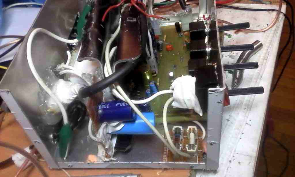
What do you mean long leads?I have connected a wire from the smoothing capacitor to a switch to the power connector on the pcb.An other wire directly from the capacitor to the gnd pin on the pcb. There is a ground plain on the pcb.
The leads are long indeed-did not cut them but rather used them as rails to the rectifier bridge.
The buzz is present even with a 12volt/4ah battery but barely noticable.
Last edited:
Hi mitsof,
And yes, there is a problem there.
The first question I always ask young technicians ... when is a ground, not a ground? This is a critical issue that needs to be understood. Let me begin by saying that any noise on your signal ground at all "looks" like an inverted version on your signal lead. The grounds that must be kept separate from each other are:
-Signal grounds
-Amplifier supply grounds (and the negative rail in this instance - they are the same thing).
-Speaker returns (common or black lead to the speaker)
-Rectifier connections to the filter capacitor(s).
If you have a shared connection between the bridge rectifier (or full wave), it will inject a particularly brutal amount of sharp hum. Anything shared on your signal common can create oscillation, hiss or any number of noises.
Draw a line from each ground type on your board using different colours. If you have more than one colour on a trace, I'd be looking for ways to divide the traces. Supply your tone stage from the main filter capacitor instead of picking up power and ground where-ever. You do want the tone signal ground to be the same as the amplifier signal ground.
Jumpers are not a bad thing to have. Always remember that the line on a schematic is actually a resistor. At higher frequencies those lines become inductive as well. I little bit of current will generate signal level voltage drops (not 0 Vu, but you can definitely hear it). Even your LED shouldn't be sitting on your signal ground.
So, signal ground is not power ground and isn't speaker return ground. See what I mean?
-Chris
Hi mitsof,
Many amplifiers isolate the signal common (or ground) with a 10 ohm to 100 ohm resistor. That can work wonders as long as the rest of the grounding is done properly. I haven't considered connections outside the amplifier.
Your input signal ground can still have problems. Just follow the idea with the colours on the board layout.
-Chris
Hi mitsof,
Many amplifiers isolate the signal common (or ground) with a 10 ohm to 100 ohm resistor. That can work wonders as long as the rest of the grounding is done properly. I haven't considered connections outside the amplifier.
Your input signal ground can still have problems. Just follow the idea with the colours on the board layout.
-Chris
Hi. in the case of tda2003, where do we have to connect the 10 ohm resistor that you said? can you pls post an image on how to do that? bcoz i also got a loud noise in my tda2003 amp, what i did is that i connect a 10K resistor in the positive input parallel to ground and the noise is gone but when i connect an RCA plug there is the noise again but it is not that loud but i think it's oscillation, here is the layout i use....
An externally hosted image should be here but it was not working when we last tested it.
If your filter capacitor has long leads, it breaks all the rules immediately.
-Chris
A chip amplifier with a ground referenced input stage and VAS running off a single power supply breaks all the rules immediately. The small signal stages on the front end share a ground pin with the collector of the low side power transistor. There's no way around it unless the chip designer pins these out individually. These circuits are already at a disadvantage noise and stability wise, even if everything else is done 'perfectly'.
Hi wg_ski,
Normally a chip amp does bring out the output supply connections. Of course with any specific ship you would look up the data sheet on it.
If you read my earlier comments to a different member you will see things like ...
-Chris
Normally a chip amp does bring out the output supply connections. Of course with any specific ship you would look up the data sheet on it.
If you read my earlier comments to a different member you will see things like ...
and other comments that might apply to this later question.So, signal ground is not power ground and isn't speaker return ground. See what I mean?
-Chris
sorry, i chose the wrong link, btw, here is the layout i used,what do you think? and help plz on how to decouple the input and output ground? tnx in advance....
An externally hosted image should be here but it was not working when we last tested it.
Last edited:
Hi Jefferson,
Okay, from post #7 above that you should have read. Here is the meat of it again.
Read the post again and think on it. There is probably other good information in earlier posts as well.
I am talking in generalities so this advice applies to all situations.
-Chris
Okay, from post #7 above that you should have read. Here is the meat of it again.
Have a good look at your layout. Actually follow this post - do it with coloured markers, pens or pencils. Crayons if you have them. Whatever you use, just follow these suggestions. You can place the decoupling resistor between the signal common and the single point ground you have designated. Hint: Make the main filter capacitor negative your official common ground point. Every single common or ground is connected to this point from a different angle and all by itself. Group the quiet grounds (signal) with like. Make certain that there is nothing between your negative capacitor terminal and the rectifiers or center tap of the power transformer. This connection should be wide and close to the positive from the capacitor to keep the large current loop as small as is reasonably possible. These connections will be all there is on that side of the solder pad. I would expect the speaker return to be high current as well. Zobel returns should go directly across the speaker pads, or from the output to the common ground point.And yes, there is a problem there.
The first question I always ask young technicians ... when is a ground, not a ground? This is a critical issue that needs to be understood. Let me begin by saying that any noise on your signal ground at all "looks" like an inverted version on your signal lead. The grounds that must be kept separate from each other are:
-Signal grounds
-Amplifier supply grounds (and the negative rail in this instance - they are the same thing).
-Speaker returns (common or black lead to the speaker)
-Rectifier connections to the filter capacitor(s).
If you have a shared connection between the bridge rectifier (or full wave), it will inject a particularly brutal amount of sharp hum. Anything shared on your signal common can create oscillation, hiss or any number of noises.
Draw a line from each ground type on your board using different colours. If you have more than one colour on a trace, I'd be looking for ways to divide the traces. Supply your tone stage from the main filter capacitor instead of picking up power and ground where-ever. You do want the tone signal ground to be the same as the amplifier signal ground.
Jumpers are not a bad thing to have. Always remember that the line on a schematic is actually a resistor. At higher frequencies those lines become inductive as well. I little bit of current will generate signal level voltage drops (not 0 Vu, but you can definitely hear it). Even your LED shouldn't be sitting on your signal ground.
So, signal ground is not power ground and isn't speaker return ground. See what I mean?
Read the post again and think on it. There is probably other good information in earlier posts as well.
I am talking in generalities so this advice applies to all situations.
-Chris
My freind why you decided mess with TDA2003.It is very old IC and low output power.Noises all you hear is 1st IC has sensitive inputs,and your transformer is not good enough for amplifier.It is so sensitive that can easyly oscilate and pick your finger gets close to it ")
I had same problem like this with TA8210 TA8215.Datasheet didnt worked.i connected in+ and in- together then it was low gain and no noise i could hear anymore .
I recommend you use TDA2052, it is much easy,more ocurate and more power 60W,it works -/+15v to -/22.5v.
I had same problem like this with TA8210 TA8215.Datasheet didnt worked.i connected in+ and in- together then it was low gain and no noise i could hear anymore .
I recommend you use TDA2052, it is much easy,more ocurate and more power 60W,it works -/+15v to -/22.5v.
Hello Batson,
His reasons are his to consider. Yes, it is an older chip and maybe more sensitive to layout, but he picked it for his own reasons.
Your suggestion to use a more current chip is maybe helpful to him, but the rest isn't helpful in his situation. He did ask for help using this part.
Hi Madaudio,
Yes, exactly. This is the message I hope Jefferson will understand and act on.
-Chris
Hello anatech
He picked thats right.we all do mistake and give wrong choises what we choose.I want to say it is never late to change to make things more better stuff.
What are you doing here is trying to rebuild useless old crab.if it was worth for that then i wouldnt recomend another,but seriously this chip doesnt worth for that.
Anatech did you tried this chip?
I think people like these old chipamps and various craptanium transistors because they are cheap and obtainable where they live and the circuits look simple and easy. Why people would want to use them or even build darlington transistor amplifiers, I don't understand but it does make for cheaper, easier DIY. Some of my friends who are quite young prefer them too, because they can buy 2 or more for the price of a modern type.
However, if you don't have the information required to apply the specific chipamps correctly, you will have trouble, as has been said. I searched the application notes and realized that the Contek data sheet, for example, does not show any PCB layout recommendations but STmicro do. Look at the recommended layout. It confirms that the grounding layout is unusual and obviously important.
http://www.st.com/web/en/resource/technical/document/datasheet/CD00000123.pdf
HTTP 301 This page has been moved
Someone, even a kit seller, could mess up here without enough study of the chip. Though a DIY PCB may not be hard, unless it follows a similar grounding format with very low resistance paths, it is bound to be noisy.
- Home
- Amplifiers
- Solid State
- Noise in my stereo tda2003 amp