I don't know how much the crossover shifts the acoustic center anyway, might need to look into that.
I've thought about that too, but beyond the delay described above I haven't investigated it.
But you're right: It would be interesting to know more about it.
As for tilting the baffle. Sure, - it certainly is the obvious way! - and the reason why I didn't is mundane and stupid enough: The feet I use for the baffe are round!
One nice thing about this basic design is it is not super sensitive as to crossover component values. Quality some what though. And with a few extra components, it is easy to tweak to suit the owners tastes and or environmental realities...
You should be fine with what you have as a starting point... As I have noted before, it's handy to start with a bit lower than stated values for the hi pass cap and pad-trap resistors and add to the cap values with inexpensive parallel .1 or .22 high voltage (200-600 V) caps until you get the balance-sound you prefer. Same with the resistors. A few extra of larger values can be easily swapped out to suit. Sometimes you will need to go back and forth between the high pass cap and pad values to get things just right. So for no more than $20 - $40 of spare parts and a few hours of listening you can really get it right for your needs.
The High pass cap range is from around 5.5 - 6.5 MFD
R1 HF trap bypass resistor range can vary from 12-25 ohms.
H.F Pad can range can vary from 7-9 ohms.
Know the above sounds a bit simplistic and redundant, but in the designing world this is usually how it's done! Good luck! John
Thanks For posting John - those values are quite a bit higher than in the original Manzanita design with the Vifa, so the newer drivers are obviously a bit hotter. Will do some experimenting and post a couple of pics once they're up and running!
Manzanita build
Ok, so I thought I would share my experience to help any other newbies to the diy speaker building caper so they don't repeat my mistake.
I knocked up a set of frames (see attached pics) as a "proof of concept" pair to listen to before going all out on fancy hardwood ply etc. Put them in the main room and hooked them up to my Naim amp and all sounded pretty good, promising. All I needed was a few crossover tweaks to fix the slightly forward mids and pad the vifa back a little to match the Peerless 12.
Shifted to another room to do the work -slightly smaller space (5x7m) and with a more reflective wall behind the speakers. Suddenly the slightly forward mid became much more pronounced with a distinct "cupped" sound around 500-600hz.
Hmm... More work than I thought. Hours later, I'm now at 12.5 ohms for the pad resistor, dialled back the cap to 4mfd to maintain the crossover point, and I'm still not hearing the seamless integration all the other posters were talking about! Time to go to bed.
Up the next day and I decided I've built something wrong. Maybe the narrow wings on the top? Weird phasing effects happening as well. So I started again. Checked all measurements, rewired the crossovers to pad at 7.5, cap at 5.6 listened and thought. Why was there so much energy coming from the vifa?
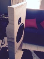
So I looked at the back. I don't own a router so I'd just filed out some lobes around the driver at around 45degrees or so to let out the rear radiation. Maybe I'd horn-loaded the back?
I carefully folded a couple of t-shirts and draped them down to damp the rear output.
Before I'd even sat down I could hear the difference. Everything now sounded right, really right! I spent around 5years working in the hifi game at the end of the 90's and heard thousands of amp/speaker combos, so I have a fair idea how things should sound, and I can tell you this design gives genuine high-end performance, as long as you build it right!
Many thanks to John Busch for the many hours I know would have gone into this design and then selflessly sharing it for all us enthusiasts.
I might post a pic of the finished product when they're done.
And just remember, don't horn-load the back of your dipoles!!
Cheers
Ok, so I thought I would share my experience to help any other newbies to the diy speaker building caper so they don't repeat my mistake.
I knocked up a set of frames (see attached pics) as a "proof of concept" pair to listen to before going all out on fancy hardwood ply etc. Put them in the main room and hooked them up to my Naim amp and all sounded pretty good, promising. All I needed was a few crossover tweaks to fix the slightly forward mids and pad the vifa back a little to match the Peerless 12.
Shifted to another room to do the work -slightly smaller space (5x7m) and with a more reflective wall behind the speakers. Suddenly the slightly forward mid became much more pronounced with a distinct "cupped" sound around 500-600hz.
Hmm... More work than I thought. Hours later, I'm now at 12.5 ohms for the pad resistor, dialled back the cap to 4mfd to maintain the crossover point, and I'm still not hearing the seamless integration all the other posters were talking about! Time to go to bed.
Up the next day and I decided I've built something wrong. Maybe the narrow wings on the top? Weird phasing effects happening as well. So I started again. Checked all measurements, rewired the crossovers to pad at 7.5, cap at 5.6 listened and thought. Why was there so much energy coming from the vifa?
So I looked at the back. I don't own a router so I'd just filed out some lobes around the driver at around 45degrees or so to let out the rear radiation. Maybe I'd horn-loaded the back?
I carefully folded a couple of t-shirts and draped them down to damp the rear output.
Before I'd even sat down I could hear the difference. Everything now sounded right, really right! I spent around 5years working in the hifi game at the end of the 90's and heard thousands of amp/speaker combos, so I have a fair idea how things should sound, and I can tell you this design gives genuine high-end performance, as long as you build it right!
Many thanks to John Busch for the many hours I know would have gone into this design and then selflessly sharing it for all us enthusiasts.
I might post a pic of the finished product when they're done.
And just remember, don't horn-load the back of your dipoles!!
Cheers
Attachments
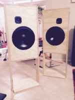
Thanks so much for telling us about your build! Glad you got the issues sorted out.
And thank you for the photos, they look very nice. John and I had talked about building the stand/legs in that way, but never did. Nice to see you did it.
If you have any photos of the back side of your mids, it might be interesting to see what went wrong there so that others don't make the same mistake.
Sorry Pano. Bought a router and now all evidence of my bodgy woodwork has gone up in a spray of sawdust.
Did do a 20-20khz sweep comparing before and after though, and all the lumpiness in response between 500-1200hz disappeared, as well as a couple of resonant peaks that nicely corresponded to the diameter of the little cup I'd managed to mount the driver in! ��
Did do a 20-20khz sweep comparing before and after though, and all the lumpiness in response between 500-1200hz disappeared, as well as a couple of resonant peaks that nicely corresponded to the diameter of the little cup I'd managed to mount the driver in! ��
Well OK, thanks for the thought. ")
John and I have both done a counter-baffle on some of our projects. I.E., cut a hole a good bit larger than the little driver, then mount that driver on a thin piece of plywood over that hole. You can flush mount the thin baffle if your woodworking skills are up to it.
It's not a bad way to do it.
John and I have both done a counter-baffle on some of our projects. I.E., cut a hole a good bit larger than the little driver, then mount that driver on a thin piece of plywood over that hole. You can flush mount the thin baffle if your woodworking skills are up to it.
It's not a bad way to do it.
My driver mounting frame just happened to be the same thickness as the chipboard panels I was using to build my second speaker way back in 1976.
I wanted to make the front flush. So I cut out the hole to fit the driver frame OD and mounted the driver to the front of a second panel glued to the back of the main front panel.
Double thickness front panel and flush fit. No rebate required, which at that time I had no tools nor skills to achieve.
Found a flaw in my layout of the Ultra crossovers. It seems the inductors weren't positioned optimally from one another.
Placement of coils in crossover networks
I've read the above article before and thought the inductor layout was optimized but hadn't been paying enough attention. Turns out the big iron inductor and wire inductors had some distance from each other but the angles were not right.
Pointed the wire inductors in a different direction and there was a nice increase in clarity. Then changed the direction of the big iron core woofer inductor and it improved again.
Very nice.
Speaking of crossover components - John has said before that the Manzanita is not too sensitive to component values, but is to component quality. I've tried a couple of different brands of caps and listening to a Dayton 5% at the moment and it sounds fairly smooth and detailed. I've played with caps in crossovers before, so have some feel for the differences they can make.
The only experience I have with changing inductors is going from cheaper iron cores to air cores in commercial speakers a couple of times. The inductor I've used in the trap is an 18 gauge with a DCR around 0.8ohm. If I were to change that to a 15awg with a DCR around 0.3ohms, apart from needing to adjust some resistor values to match the output again, what qualitative difference if any would there be? Would cost around $ 80Aus to do.
Cheers
I have read this entire thread and want to make these. I wanted to do a little listening area with a turntable. I was going to use some DLK 1's or 2's that I own and have restored (they have alnico magnets too) but am now thinking this would be better, how would you say they'd compare?
-Can the wings be put on the backside of the baffle to give the front a cleaner look? I would keep the same overall dimensions.
-I believe this is the most current parts list right?
L1 inductor. 18-22 MH Iron core. 15-16 ga. PE P/N 266-960 (16 ga. 20 MH)
L2 H.F. trap inductor 2.75 MH air core PE P/N 266-836
C1 H.F. 1st order electrical high pass capacitor. 6.0 MFD. PE P/N 027-236
R1 HF trap bypass resistor... 15.0 ohm, 5-10 watt P/N 015-15
R2 H.F Pad...8.0 ohm, 5-10 watt PE P/N# 016-8.2
Woofer. GRS-15PF-8 15" woofer. PE P/N 292-415.
Mid-tweeter. Vifa TC9FD18-08. PE 264-1062
Yep, mostly right. I know that the HF section has undergone some refinements since I posted the schematic. Looks like you found some of those changes. John can weigh in on the current values. I have found that it takes some adjusting depending on your room. What works for me, doesn't always work for someone else. Be prepared to tune. The low pass 20mH is a constant, tho.
Yes, you can put the wings in the back, just keep the overall dimension close, or be prepared for even more tuning.
Yes, you can put the wings in the back, just keep the overall dimension close, or be prepared for even more tuning.
Hi!
Here is picture about my almost ready baffles. I ordered veneer from Aliexpress (too small amount, not enough for backsides ) and local carpenter made veneering. Need to do finish for veneer, burn or paint backsides and make digital xo solution / or more familiar passive which i already tried with satisfaction with my test baffles.
I would like to try Manzanita´s with my Powerbox amp from Magiclx521 consisting: 4x Hypex Ucg180HG and Hypex DLCP digital XO. I use it currently with my Lxmini speakers and could try with M´s also. However, I have not used RTA or digital xo devices besides minidsp before. Any comments available from users who has knowledge how to transport Manzanita passive xo to digital biquads ?
Here is picture about my almost ready baffles. I ordered veneer from Aliexpress (too small amount, not enough for backsides
) and local carpenter made veneering. Need to do finish for veneer, burn or paint backsides and make digital xo solution / or more familiar passive which i already tried with satisfaction with my test baffles. I would like to try Manzanita´s with my Powerbox amp from Magiclx521 consisting: 4x Hypex Ucg180HG and Hypex DLCP digital XO. I use it currently with my Lxmini speakers and could try with M´s also. However, I have not used RTA or digital xo devices besides minidsp before. Any comments available from users who has knowledge how to transport Manzanita passive xo to digital biquads ?
Attachments
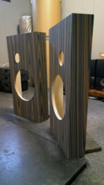
Very nice looking baffles! Thanks for the photo.
I have run the Manzanita with digital crossovers, but I could never get it to sound quite right. There are different approaches, imitate the passive, do active EQ, try both. The passive version always sounded better to me. However, you might be able to do a better job than I!
I have run the Manzanita with digital crossovers, but I could never get it to sound quite right. There are different approaches, imitate the passive, do active EQ, try both. The passive version always sounded better to me. However, you might be able to do a better job than I!
A starting point for an active crossover would be:
Low Pass on woofer. 2nd order Butterworth @ 80Hz
High pass on Vifa 1st order @ 1200Hz
Notch/shelf on Vifa 1st order low pass @ ~2000Hz
or try a HP shelf at 2Khz lowering the top end of the Vifa
Yes, those points seem very wrong, but that's what works in Open Baffle.
Low Pass on woofer. 2nd order Butterworth @ 80Hz
High pass on Vifa 1st order @ 1200Hz
Notch/shelf on Vifa 1st order low pass @ ~2000Hz
or try a HP shelf at 2Khz lowering the top end of the Vifa
Yes, those points seem very wrong, but that's what works in Open Baffle.
- Home
- Loudspeakers
- Multi-Way
- Fast, fun, Inexpensive OB project