I would have thought that would be rather difficult. Pentodes have very high plate resistances which makes them unsuitable for transformer-less output stages.
Cheers
Ian
Hmm, I thought that pentodes being more efficient than triodes would mean that they would work better in transformer-less output stage, but I guess it's not true if they have significantly higher output impedance than triodes.
Hmm, I thought that pentodes being more efficient than triodes would mean that they would work better in transformer-less output stage, but I guess it's not true if they have significantly higher output impedance than triodes.
Not sure where you get the idea they are more 'efficient' than triodes. The efficiency comes from the topology they work in, not from the tubes themselves.
Cheers
Ian
Not sure where you get the idea they are more 'efficient' than triodes. The efficiency comes from the topology they work in, not from the tubes themselves.
Cheers
Ian
Hmm, what do you mean? For example, you can get more power from a pair of pentodes in push-pull output stage, than you would if they were strapped to triodes.
Hmm, what do you mean? For example, you can get more power from a pair of pentodes in push-pull output stage, than you would if they were strapped to triodes.
Which not the same as efficiency. Efficiency is output audio power as a proportion of dc input power. In a push pull amplifier this is determined mainly by the class of operation. A class A amplifier can never be more than 25% efficient. A class B amplifier can never be more that 70% efficient no matter whether it is a triode, pentode or semiconductor.
Cheers
Ian
Yes, those are the theoretical maximums (though maximum for class A is 50% if transformer coupled), but as far as I know, you are likely to get closer to them with pentodes rather than triodes. Or even better, with transistors.
Member
Joined 2009
Paid Member
This circuit can deliver ~1.3V rms into 32 ohm, which may or may not be enough, depending on the sensitivity. If it's >100dB/V (which many cans are), it's probably sufficient.
1.3V into a pair of Grado's will confir deafness, you want an order of magnitude less voltage I believe.
How much coupling cap leakage current is acceptable ?
There is the rule of ten.
If your headphones are 150Ω you want a headphone amp with less than 15Ω output impedance.
The O2 headphone amp has a .5Ω output impedance and it can drive my 18Ω Sennheisers with great authority.
Keep this in mind.....just a rule of thumb.
I'd be more inclined to use a multi-tapped matching transformer at the output or an opamp buffer for driving headphones with any reasonable level of control over the bottom end.
There is the rule of ten.
If your headphones are 150Ω you want a headphone amp with less than 15Ω output impedance.
The O2 headphone amp has a .5Ω output impedance and it can drive my 18Ω Sennheisers with great authority.
Keep this in mind.....just a rule of thumb.
I'd be more inclined to use a multi-tapped matching transformer at the output or an opamp buffer for driving headphones with any reasonable level of control over the bottom end.
According to this, many headphones work well with a 120 ohm series resistance: Headphone Amplifier
I guess something like that should be achievable with a cathode follower and negative feedback..
Anyways, my friend's headphones are 250 ohms..
PRR's observation that '7V behind 29 ohms will drive "any" headphone' is a useful rule of thumb.
summing speaker/power signals, help !
summing speaker/power signals, help !
According to this, many headphones work well with a 120 ohm series resistance: Headphone Amplifier
I guess something like that should be achievable with a cathode follower and negative feedback..
Anyways, my friend's headphones are 250 ohms..
Many people confuse output impedance with drive capability. It is not too hard to make a cathode follower with a lowish output impedance. The standard formula for this is 1/gm for a cathode follower and, depending on the tube used, results in a calculated output impedance of a few hundred ohms or less. With additional negative feedback this can be reduced still further. However, it is important to remember that these formulae apply ONLY to small signal conditions. The volt or so you need to drive 250 ohm headphones is NOT a small signal and these formulae no longer apply.
Cheers
Ian
Member
Joined 2009
Paid Member
... my friend's headphones are 250 ohms..
Perhaps you could get away with a White Cathode Follower, where Zout is more like 1/2gm. Using a 6DJ8 (=ECC88) with both halves in parallel you'll get a Zout of roughly 1/4gm which might just work. You'll want to run it at fairly high current in order to get a good gm and ensure that there's sufficient current for the load.
With 250R phones, perhaps their sensitivity means you don't need any more than 10mW of power ? - and you'd be unlikely to need more than 10mA of current into the phones. That's well within the capability of a doubled-up 6DJ8 which you might run at 15mA per side, total 30mA for a doubled-up for each channel. Providing there's enough current I don't see any issue with there being enough drive capability. Plus these tubes are reported to work at reasonably low plate voltages too.
This is all theoretical, I've never built anything like that myself. My phones are 32 Ohm so I'd not contemplate this approach myself.
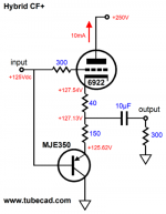
Edit: Here's another option for a hybrid that borrows the high gm of a transistor for lower output impedance. I've never seen a report of anybody who has built it so no idea of the sound or any complications.
Brains & Brawn Cathode Follower
Attachments
Last edited:
Many people confuse output impedance with drive capability. It is not too hard to make a cathode follower with a lowish output impedance. The standard formula for this is 1/gm for a cathode follower and, depending on the tube used, results in a calculated output impedance of a few hundred ohms or less. With additional negative feedback this can be reduced still further. However, it is important to remember that these formulae apply ONLY to small signal conditions. The volt or so you need to drive 250 ohm headphones is NOT a small signal and these formulae no longer apply.
Cheers
Ian
But what about this: The Morgan Jones Mini Tube Headphone Amplifier | HeadWize
Also, would it be reasonable to replace the output cathode follower with ECC82? I have been under the impression that while not good in audio in most roles, it will work fine as a cathode follower.
Apparently it seems like it would be possible to drive reasonable amount of power even to 32 ohm headphones. About 10mW should be enough for headphones, after all..
Last edited:
Member
Joined 2009
Paid Member
This is another relatively simple one (I'm actually quite tempted to build this one myself, I'm currently looking for a unity gain headphone amp)
Hybrid Headphone Amplifier | EEWeb Community
Hybrid Headphone Amplifier | EEWeb Community
Last edited:
No, it cannot supply enough current to drive headphones.Also, would it be reasonable to replace the output cathode follower with ECC82?
A White CF using an ECC88 (such as Morgan Jones) can deliver about 10mW into 50 ohm phones or 100mW into 300 ohm phones, with <1% THD. Into 32 ohms you *might* just get 10mW with less than 5% THD... An ECC82 would fail miserably on all counts.Apparently it seems like it would be possible to drive reasonable amount of power even to 32 ohm headphones. About 10mW should be enough for headphones, after all..
Last edited:
No, it cannot supply enough current to drive headphones.
ECC82's maximum current rating is 20mA, while ECC88 is 25mA. Hardly a big difference, so what makes it so bad?
A White CF using an ECC88 (such as Morgan Jones) can deliver about 10mW into 50 ohm phones or 100mW into 300 ohm phones, with <1% THD. Into 32 ohms you *might* just get 10mW with less than 5% THD... An ECC82 would fail miserably on all counts.
If you read my link, with ECC88 the optimized version with NFB put 10mW to 32 ohms at 1.4% THD.
ECC88 can deliver a lot more peak current (and with a lot less voltage drop across it). I suppose an ECC82 White CF with a 400V supply might just mange it, though it would be frightfully inefficient.ECC82's maximum current rating is 20mA, while ECC88 is 25mA. Hardly a big difference, so what makes it so bad?
Yes that's with global NFB to reduce the distortion.If you read my link, with ECC88 the optimized version with NFB put 10mW to 32 ohms at 1.4% THD.
Last edited:
- Status
- This old topic is closed. If you want to reopen this topic, contact a moderator using the "Report Post" button.
- Home
- Amplifiers
- Tubes / Valves
- Tube headphone amp