I have some proper resistors coming. Yes, you can parallel resistors to get a specific lower value. Since I am using a spanky new PCB, I just prefer a cleaner and less cluttered look than 3-4 resistors stacked on top of each. But that's just me and my 'anal' approach to most things.I just use 1r0, 600mW, 1%, 100ppm, metal film in parallel combinations, rather than stock lots of low value, high wattage Re types.
2off 1r0 = 0r5, 1.2W
3off 1r0 = 0r33, 1.8W
4off 1r0 = 0r25, 2.4W
5off 1r0 = 0r2, 3W
6off 1r0 = 0r17, 3.6W
and all are <1% tolerance with 100ppm tempco.
If higher dissipation is required for 0r5, I would use series/parallel combination.
") I prefer a less hacked look unless it's unavoidable. Yeah, I know, not very DIY.
I prefer a less hacked look unless it's unavoidable. Yeah, I know, not very DIY. Gentlemen, I have been asked to provide you a better readable picture of the SYMASYM's backend PSU-schematic.
Find it attached.
As R45/R47 you can either use a 0R1- or 0R22||0R22 resistor - or:simply leave it (solder a wire instead).
Several of my German SYMASYM-friends say that the SYMASYM sounds more "dynamically" without this resistor(s) - but I doubt this.
Best regards - Rudi_Ratlos
Find it attached.
As R45/R47 you can either use a 0R1- or 0R22||0R22 resistor - or:simply leave it (solder a wire instead).
Several of my German SYMASYM-friends say that the SYMASYM sounds more "dynamically" without this resistor(s) - but I doubt this
.Best regards - Rudi_Ratlos
Attachments
Thanks Rudi. Much more readable than the small image in the build guide. I can actually see the component values now.Gentlemen, I have been asked to provide you a better readable picture of the SYMASYM's backend PSU-schematic.
Find it attached.
As R45/R47 you can either use a 0R1- or 0R22||0R22 resistor - or:simply leave it (solder a wire instead).
Several of my German SYMASYM-friends say that the SYMASYM sounds more "dynamically" without this resistor(s) - but I doubt this
Best regards - Rudi_Ratlos
Rick
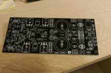
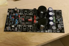
Here's a couple images of my build. Just one board at the moment. Still waiting for a few more parts to come in. The images are larger than I wanted, but I'm at my smallest size and max compression and you still have to scroll around to see the entire picture. I may switch over to uploading all my build pictures to my public PhotoBucket account where you can view images in all their hi-res Lumix glory.
Rick
Rick
Attachments
post1202
remove the GND symbols and replace with Transformer Centre tap symbols.
Move the right hand centre tap symbol from the middle of the PSU capacitor group, to the extreme left hand end of that Zero Volts rail.
R43 and R44 are on the wrong side of the supply rail fuses. If you think you need them. I would not fit them, they just increase ripple fed to the ClassAB amplifier.
I have a feeling that R40 & R42 are too low to be effective in snubbing the transformer ringing. They also need to be mounted close to the transformer leads, i.e. at the ~~ on the rectifier where X2-4 and X2-1 from the transformer feed into the rectifier.
Andrew, for EAGLE (the layout-editor that I am using) SV1-4 is just a 4-pole PCB connector (from Amphenol, Phoenix,...), and I must tell EAGLE to which track to connect the 4 poles.
EAGLE is not aware of the fact the SV1-4 connect to a transformer with 2 secondary windings or a center-tapped transformer.
I have described in the SYMASYM's Builder's Guide how to connect the used tramsformer to this PCB-connector in detail.
I have moved the "bleeder" resistors to the front of the fuses in my current layout.
Best regards - Rudi
P.S. Rick: as far as I can see, you have done a good job so far.
Please do not forget and put a cap on jumpers JP1 and JP2.
Last edited:
Rudi - A couple of questions about the Black Beauty boards...
(1) This may be a dumb question, but I just want to make sure before I mount the 2 sets of MUR820G rectifiers to a single heatsink. Does the bolt need to be insulated from the devices and heatsink? I can't see anyway of doing. If not, can the two devices be connected together without issue? I assume so, but thought I'd ask first.
(2) There are 4 sets of 2 holes (One with a white circle around it.) They are located between the output transistors and the MJE devices. They're labeled as 1.2. What device is this? Ah ha. I think I see them on the schematic. Are they R22, R24, R35 and R80?
Rick
Rick, the bolts of the heatsinks aren't connected to any track and you can safely solder them to the surrounding solder-pads.
However: the MUR - diodes need to be insulated, since their metal back is connected to the cathode of the diode.
The resistors that you are mentioning, are base-stoppers and need to be mounted vertically.
Best regards - Rudi
However: the MUR - diodes need to be insulated, since their metal back is connected to the cathode of the diode.
The resistors that you are mentioning, are base-stoppers and need to be mounted vertically.
Best regards - Rudi
For the base stopper resistors I want to be very clear on their value. 1.2 = 1.2 Ohms, correct? Is there a difference between 1.2 and 1R2? The period . and comma , often get lost on some schematics so, I'm trying to understand the new nomenclature since I'm very old school and learned the color-coded way. But I know this new value marking has been around a while now too. 1.2 DOES NOT equal 1,2. 1,2 could also be written as 1k2?I just use 1r0, 600mW, 1%, 100ppm, metal film in parallel combinations, rather than stock lots of low value, high wattage Re types.
2off 1r0 = 0r5, 1.2W
3off 1r0 = 0r33, 1.8W
4off 1r0 = 0r25, 2.4W
5off 1r0 = 0r2, 3W
6off 1r0 = 0r17, 3.6W
and all are <1% tolerance with 100ppm tempco.
If higher dissipation is required for 0r5, I would use series/parallel combination.
And it I just want to use a single 1.2 resistor, what wattage rating should it be? 1/2w, 1watt, 2watts ? I'm guessing the tolerance factor should be 1% too.
for resistors and some other components, a recognised method of inserting both the decimal separator and the multiplier is to use the multiplier symbol as the decimal separator.
This avoids lost decimal separators and saves a keystroke.
eg 1.2ohms can be misread as 12 ohms, similarly .22ohms can be misread as 22r.
whereas 1r2 and 0r33 cannot be misread and both use fewer keystrokes.
1k2 is 1200r and could be typed as 1.2k ohms or 1,2k ohms. All three of these option are longer and no clearer than 1k2.
The comma used as a decimal separator is generally only used in Continental Europe. I find that causes me a lot of confusion. I usually have to re-read to try to work out what value they have actually meant us to understand from what they type.
This is one example where 1,200 ohms would be very confusing. Would the context help with solving the puzzle set by the continental typer?
M, k, p, n, µ & m get used very regularly.
I could have used the W (watt) as my decimal separator and although I would argue that as correct usage it is relatively rare and may confuse others if I were to be that pedantic.
Never omit the leading 0 (zero) for values below 1 (one)
Never use m for micro, that's a very old standard that is no longer used.
Never us K (Kelvin) for kilo (10^-3)
Last edited:
So, if I read 1.2 on a schematic with no other markings, it means its value is 1.2 Ohm and could also have been marked as 1R2 ?for resistors and some other components, a recognised method of inserting both the decimal separator and the multiplier is to use the multiplier symbol as the decimal separator.
This avoids lost decimal separators and saves a keystroke.
eg 1.2ohms can be misread as 12 ohms, similarly .22ohms can be misread as 22r.
whereas 1r2 and 0r33 cannot be misread and both use fewer keystrokes.
never omit the leading 0 (zero) for values below 1 (one)
Sorry, I meant to write 1r2.capital R would be for a unit that is named after the person. As evidenced by Watt, Kelvin, Celsius, Fahrenheit, Seimens, Hertz, etc.
I can't think who that would be. Laminar air flow perhaps?
Little r would be used when the multiplier value is 1.
Going on,
Ohm is correct. It is after the person.
But I find that reading 10Ohm quite difficult, as would be any resistor value that ends with a zero.
I prefer, even though I know it is wrong, to type 20ohm, or 100ohm, since I find that much easier to read, cf. 20Ohm, or 100Ohm.
Can we be excused for breaking the rules by adopting a non standard o instead of O when the o makes it easier?
My opinion is that it helps avoid mistakes.
Some may come back and suggest there should be a space between the value and the unit, but I was taught to not insert a space.
Any comments?
Last edited:
Going on,
Ohm is correct. It is after the person.
But I find that reading 10Ohm quite difficult, as would be any resistor value that ends with a zero.
I prefer, even though I know it is wrong, to type 20ohm, or 100ohm, since I find that much easier to read, cf. 20Ohm, or 100Ohm.
Can we be excused for breaking the rules by adopting a non standard o instead of O when the o makes it easier?
My opinion is that it helps avoid mistakes.
Some may come back and suggest there should be a space between the value and the unit, but I was taught to not insert a space.
Any comments?
Thanks for sharing your insight. But since I've been away from this for decades you can take my comments with a grain of salt. I have not been in the industry at all. It was a hobby in the 60's, and it is now, 50 yrs later.
I can't remember the specifics of whether Ohm was spaced away from the value or not when I was being taught this basic stuff in the late 60's, but in my mind it makes it clearer as to the value. I much prefer to use the word ohms myself, but alas, times change, but I'm not convinced it's always for the better.
There is no interpretation needed. 10 Ohms is 10 Ohms. 10k Ohms is 10,000 Ohms. Seems pretty clear to me. And 1.5k Ohms is 1,500 Ohms. Why confuse the decimal and comma? Interestingly, Mouser still refers to all resistor values on their package labeling in the old fashion way 100ohms, or 100 OHM never 100r, or 3k3. I just get confused as heck to refer to 1,5 the same as 1k5 as 1.5k ohms as 1,500 Ohms. There really is no confusing the last 2 or where the DECIMAL place should be.
Sorry to get off-topic.
Rick,
this is written about the combination of Vishay MKT1822 MKT and MKP1837 in "Humble Homemade HiFi":
Technical specifications of MKT 1822: Metallized polyester film with vacuum deposited aluminium. Main applications: blocking, bypassing, filtering, timing, coupling and decoupling circuits, interference suppression in low voltage applications.
Sound: Well balanced, overall coherent sounding capacitor. It doesn't have as much depth as the more high-end type capacitors and micro-detailing is limited but somehow it did stay in the back of my head as nice and pleasent to listen to.
You can boost the overall presentation a lot by adding 0,01uF's worth of MKP1837 parallel. So if you are looking for a cost effective and very compact alternative to MKP capacitors like the Solen Fast Cap, look no further!
I myself am very happy with this combination.
Best regards - Rudi
- Home
- Group Buys
- TO-3 SYMASYM