Hi All
I did an impedance measurement of my FE208E Sigma driver fitted in my Dallas2 horn over the weekend.
The result is shown in the picture attached.
Can anyone tell me what is the cause/meaning of the two resonances (eg is it one for the driver and one for the tuning of the horn?) and do I need to do anything about them from the points of view of audibility and loading of the amplifier? (I'm using an 8W SET amp).
If so, I can work out what network to use to null it out electrically, but have no idea how to tame any acoustic resonance (other than by trying various positions of wadding).
Thanks in advance for any help
Chris
Attachments
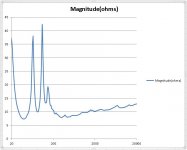
The response multiple peaks is to be expected for a back loaded horn. Take an inpedance measurement with driver in free air and you will see the contribution of the cabinet - which is substantial. The tuning freq fb of your horn is the inpedance minimum between the two peaks on the left.
There is the xsim software package from Bwaslo for designing XO's and filters to help flatten the peaks. Your SET amp is probably able to handle high inpedance loads.
There is the xsim software package from Bwaslo for designing XO's and filters to help flatten the peaks. Your SET amp is probably able to handle high inpedance loads.
do you think you've missed hearing some horrible anomaly that the graph suggests must be there?
Exactly that! I'm an engineer; if the measurements say there's something wrong and I can't hear it, then either my ears are no good or I'm not listening properly or both.
")
Actually I've been experimenting for about a week with room positioning, wadding and crossovers, the latter being the reason for wanting to know the actual driver impedances.
Areas I'm trying to improve are:
1. Imaging at high frequencies - it's all over the place at the moment and I'm hoping I can rectify that with the correct crossover arrangement.
2. Low frequency response - so far I've either got too much mid bass making the sound boomy and speech coloured, or too little making the sound a bit thin. I'm hoping I can rectify this with further experimentation with stuffing and speaker position, although maybe it's in the nature of horns?
I asked about the impedance peaks for two reasons:
1. In case someone (who knew what they were talking about) said "you will never get the bass to sound right until you sort that out", and
2. In case someone (who knew what they were talking about) said "you will need to correct those peaks in order to avoid over-volting the tubes in your SET amp"
How will I know whether they know what they are talking about? I guess I'll just have to see whether their explanations convince me!
Exactly that! I'm an engineer; if the measurements say there's something wrong and I can't hear it, then either my ears are no good or I'm not listening properly or both.
Or the measurement is not telling you the whole story.
The graphs are a pretty much as expected. The bigger peaks are as you would expect from a box with a hole in it. The little peak is eveidence that the 1st undesirable harmonic is not completely suppressed (there is actually a train of them but the impedance curve shows that they are well controlled). Some carefully placed damping might well further suppress that small 3rd peak.
With a high output impedance amp (yours a 300B SE?), the the power output will increase somewhat as the impedance rises, the lower impedance peak is already below where the speaker is rolling off so pretty much out of the picture. The middle one in conjunction with the amp will extend the bass response somewhat. The smallpeak will cause some ripple in the FRm something seen in every quarter-wave speaker. These are all in the region where the room dominates so any pertebations from the amp/speaker are likely buried under room effects.
All speakers are aset of tradeoffs. What is important in the end is if the system can connect you emotionally to the music.
dave
with the correct crossover arrangement
Crossover? With the sigma that is likely to be a single cap on a horn tweeter to help fill in the top 2 octaves. Andmaybe some R to pad the tweeter.
Can you post a pictureof the tweeter/sigma arrangement.
I believe there are some suggested small changes to the air cavity volume to better optimize the sigma to a box optimized for the FE206e.
dave
Hi
Thanks for the replies.
Yes, the amp is a 300B.
Regarding the crossover; I started off with just a cap and a resistor pad (actually a selection of each that I could switch in and out to find my preference, making sure each pad had an appropriate shunt to ground to keep total impedance seen by the cap constant), but I'm finding that for any part of the audio spectrum that calls on the tweeters, the image is lost and the sound retreats right back to the speakers.
It's a strange effect and a bit of searching and reading led me to think it could be due to phase difference between the same frequencies coming from the tweeter and main driver simultaneously. That is leading my down the route of trying higher order crossovers. A second order has indeed improved the situation but the sound is still not as "integrated" as I think it should be.
You will see that the tweeters and main drivers are not mounted particularly close together, but that's as close as they can be if I'm to use the redundant cavity above the main air cavity for the tweeter.
I also realise the clamps may affect things but would they affect the tweeters more than the midrange?
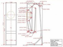
I believe the mods for the FE208E Sigma are the piece fitted right behind the driver, and the one in the top of the upside-down U in the second photo and have been included in my build.
I have lined the cavity with carpet underlay as I read somewhere that it was the right thing to do.
If any of what I've done is not correct or doesn't make sense, or if you've got any other advice it would be very gratefully received.
Thanks again to all who take the time to reply
Chris
Thanks for the replies.
Yes, the amp is a 300B.
Regarding the crossover; I started off with just a cap and a resistor pad (actually a selection of each that I could switch in and out to find my preference, making sure each pad had an appropriate shunt to ground to keep total impedance seen by the cap constant), but I'm finding that for any part of the audio spectrum that calls on the tweeters, the image is lost and the sound retreats right back to the speakers.
It's a strange effect and a bit of searching and reading led me to think it could be due to phase difference between the same frequencies coming from the tweeter and main driver simultaneously. That is leading my down the route of trying higher order crossovers. A second order has indeed improved the situation but the sound is still not as "integrated" as I think it should be.
You will see that the tweeters and main drivers are not mounted particularly close together, but that's as close as they can be if I'm to use the redundant cavity above the main air cavity for the tweeter.
I also realise the clamps may affect things but would they affect the tweeters more than the midrange?
I believe the mods for the FE208E Sigma are the piece fitted right behind the driver, and the one in the top of the upside-down U in the second photo and have been included in my build.
I have lined the cavity with carpet underlay as I read somewhere that it was the right thing to do.
If any of what I've done is not correct or doesn't make sense, or if you've got any other advice it would be very gratefully received.
Thanks again to all who take the time to reply
Chris
Attachments
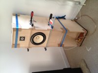
I am always leary of how well clamps actually seal the side to the rest of the box. Any leaks can cause some issues.
The tweeter (FT96?) should be as close as possible to the FE208. You will never get it withing 1/4 wl centre-to-centre but as it is now, you move your head at all phasing will change. Mount them mirror image above & to the side.
XO near 5k?
Is the carpet underlay natural (ie wool) or synthetic?
dave
I am always leary of how well clamps actually seal the side to the rest of the box
I know what you mean, although I have also used draught excluder strip around the critical parts to try to eliminate problems as much as possible.
as it is now, you move your head at all phasing will change
I did fear this, but as moving them is a problem for which a solution I have yet to come up with (because the back of the tweeter will foul on the internal baffles, or encroach on the main cavity or both), I was leaving this as a last resort!
Some quick geometry calcs today suggest that from my listening distance, if I move my head 10cm, the relative distance between the drivers will change by, at most 1mm. This corresponds to about 10 degrees of phase change at 10kHz. Would this be audible?
XO near 5k?
I found 3u3 to sound about right, which into 8 ohms gives -3dB at ~6khz. Not sure whether -3dB is definitively the XO point but close anyway.
Is the carpet underlay natural (ie wool) or synthetic?
I think synthetic - it seems to be made of compressed small pieces of foam.
I've also got some Monacor wool wadding to experiment with. At the moment I've got some of that on the outside radii of the folds in the horn.
This evening I'm trying some crossover values (2nd order) that I've arrived at by simulating in spice then applying the response mathematically to the drivers' published frequency responses in exel and tweaking to get a theoretically flat response. It's seems to be working quite well so far - definitely getting closer to the sort of sound I was hoping for. I think I still might need to tame the mid/upper bass a bit though as I've got the speakers a fair way from the wall and it's still a bit much.
Thanks again!
Chris
I think synthetic - it seems to be made of compressed small pieces of foam.
I've also got some Monacor wool wadding to experiment with. At the moment I've got some of that on the outside radii of the folds in the horn.
I would get the tweeter closer. The volume the back of it will take up is not significant.
Trash the synthetic underlay. Ideally cotton or wool felt... 12mm or so is good
dave
Removing the underlay made quite an improvement thanks.
It looks like I can move the tweeter down about 40mm without too much difficulty.
Regarding the offset - is the objective to equalise the path length from the two drivers?
If so, the amount and direction of offset would be dependent on the toe-in of the speakers.
If it's for a different reason can you offer any guidance on how much and in which direction to make the offset?
Many thanks again
Chris
Regarding the offset - is the objective to equalise the path length from the two drivers?
You mean the distance between the drivers? Idealing the centre-to-centre should be a quarter-wavr length or less at the XO frequency, given that you are not going to get close to that goal, getting them as close together as you can makes sense.
Most of the multiway systems we do have the XO quite low where a 1/4 wl is possible, but when i am doing one that is not, if possible, i will carve the tweeter bezel to get the tweeter just that much closer to the FR ormidbass.
The effect the XO plays on phase and the room (in a different way) affect the response. With a mirror image pair you can play with tweeter inside of outside to see what works best with these variables.
dave
Update:
I bit the bullet and moved the tweeter. Glad to say it has made a noticeable improvement and I'm pretty happy with the top end performance now.
My "mid-bass" problem is persisting though. After a lot of listening and experimentation with stuffing and room position, I haven't been able to tame a resonance which, on a lot of tracks is pretty intolerable and on one or two hoots horribly.
I finally got the mic out and fired up ARTA to see whether it could tell me anything (even though I can't get the speakers far enough from boundaries to do accurate measurements at those frequencies).
A combination of measuring, listening, EQing and reviewing of the Z plots tells me pretty conclusively that there's a resonance at 158Hz causing the problem. If I notch it out with an equalizer app (6dB down at centre, 1dB down at 100Hz/250Hz) it solves the problem and all the tracks I could try in one evening sounded superb.
What I'm wondering now is: Can this be controlled/fixed mechanically or do I need to make a passive notch filter? The latter is less preferred as it seems like a sticking plaster rather than a fix. It will also be difficult due to the variations in the load impedance around this frequency, not to mention the size of inductors required.
I have done some searching but not really found anything that looks like it might be a recipe for a cure.
Thanks for reading!
Chris
You can tame resonance peaks with a 1/4-wave stub filled with stuffing. Ideally the stub should communicate with the rear driver chamber upstream of the horn throat. However, 158Hz will require a 21.3 inch long closed end stub. You can do a quick experiment by getting some 3in PVC pipe with a cap cut to this length. Stuff it with fiberglass/Rockwool. Cut a hole in your driver chamber and attach the stub. Adjust stuffing and peak should go down noticeably. If building same BLH from beginning, add design into box with folded stub same width as speaker and maybe 1in high x 21.3in deep.
re listening tests with clamped up boxes - I've always been concerned that the mass and torque of the clamps would add yet another variable to the equation, and would change the resonant frequencies and damping characteristics of the enclosures. When removed, the boxes might not sound the same?
I've always used foam weatherstripping tape and screwed the second side panel on for any such tests.
I've always used foam weatherstripping tape and screwed the second side panel on for any such tests.
- Status
- This old topic is closed. If you want to reopen this topic, contact a moderator using the "Report Post" button.
- Home
- Loudspeakers
- Full Range
- Twin Peaks - Impedance measurement advice needed!