What bothers me with unity gain is leaving R16 and in particular C19 in circuit. Normally for unity gain you would just link the opamp output and the inverting input together. Now it will certainly work leaving these feedback components in place but unless I tried it with that opamp type I wouldn't like to say it was optimal. You could find the squarewave response a little peaky.
That's it(you mean keep R21) You can't damage anything altering these resistors, you will just have to try the different gains and settle on what works best. I know that sounds unscientific but its just not possible to calculate the gain you need for your headphones.
Its try it and see.
Yes, I should keep R21 shouldn't I?
Thanks for your help.
What bothers me with unity gain is leaving R16 and in particular C19 in circuit. Normally for unity gain you would just link the opamp output and the inverting input together. Now it will certainly work leaving these feedback components in place but unless I tried it with that opamp type I wouldn't like to say it was optimal. You could find the squarewave response a little peaky.
Hmm...interesting although I really don't have the means to test this and observe the square wave.
I may go ahead and play with the resistors and lower gain but not completely remove the resistors....
Anyone?To the engineers around here!:
Having built a low power version of the O2 with the OPA2277/TLE2062 combo, the recommended changes to gain resistors, compensation caps and output resistors, I was wondering what would happen if I decided to swap the op amps back to the "original" ones without changing the other components back.
Would there be any measurable objectionable differences (let alone audible ones) compared to an "stock" O2 with the 2068/4556?
I know the output impedance would be about 3.2 ohms instead of 0.5, but the hphones I use are Beyers DT-250 80 ohms and DT-770 250 ohms so I guess no big issue there?
I do have another question though!.. although this might be the wrong thread... I'll shoot anyways!
I have built in an ODAC into my O2, it is connected to the input jack's pins, in order to switch between sources. I have also mounted the output jack on the ODAC, to connect powered monitors.
The thing is, I get distorded sound out of the ODAC's output jack whenever the O2 is switched off. "Disconnecting" the O2 from the ODAC by plugging in an open cable to the input jack solves the problem.
I guess the unpowered O2 is loading the ESS9023's ouput buffer beyond its capability, but what is the logic behind that? And why does the problem disappear when the O2 is on?
Many opamps exhibit this behaviour when switched powered down. The reason is often input protection diodes within the chip that are no longer reverse biased by the power supply and so appear as a non linear and low impedance load.
Were R7 higher in value then the effect would disappear.
Yes, I should keep R21 shouldn't I?
Thanks for your help.
Yes, keep R17 and R21
Hmm...interesting although I really don't have the means to test this and observe the square wave.
I may go ahead and play with the resistors and lower gain but not completely remove the resistors....
The usual way to set the O2 to 1x is to simply remove the gain resistor. I don't have the equipment to test how the amp responds to this, though.
I might post a bit more on the subject of gain on the 02. There are different ways to reduce the gain, and some may give a much better result than others. Many opamps, although 'unity gain stable', offer better subjective performance when not used in this way. That is why I suggested increasing the input resistor as another possible solution.
Please do, that would be very interesting!I might post a bit more on the subject of gain on the 02. There are different ways to reduce the gain, and some may give a much better result than others. Many opamps, although 'unity gain stable', offer better subjective performance when not used in this way. That is why I suggested increasing the input resistor as another possible solution.
I listen to the O2 a lot att gain setting 1x, since I feel I get the most of the volume pot's range at that setting. Comfortable volume with my cans is at 2 o'clock at gain 1x.
Last edited:
The 02 Input Circuit and Gain Settings.
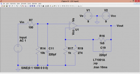
This shows the O2 input circuit and the two switchable gain setting resistors.
Input Circuit

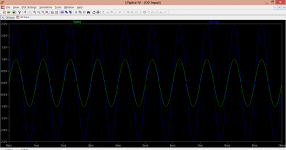
With an applied voltage of 1 volt peak we can see that the output agrees with the calculated 2.5 or 6.5 gain. Note the input voltage and the output voltage marks at the top of the trace and the corresponding scale at the left.
Low gain setting with the 1k in switched into circuit.

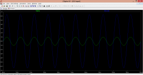
High gain setting with the 274 ohm switched into circuit

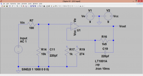
The simplest unity gain configuration is this which simply removes the lower feedback resistor from the network leaving R16 and C19 in circuit.
Simple Unity Gain Configuration

And the corresponding input and output levels.

For best performance and sonics this could be a preferred configuration. We retain the feedback network and alter the input resistors.
Possible preferred configuration

This shows the output voltage now lower than the input (less than unity gain). Although this breaks the rule of 'attenuate and then amplify', the advantages overcome the downsides. The noise penalty for this approach is absolutely minimal and it keeps the opamp working at a reasonable closed loop gain. In my opinion that is best for sonics.

This shows the O2 input circuit and the two switchable gain setting resistors.
Input Circuit
With an applied voltage of 1 volt peak we can see that the output agrees with the calculated 2.5 or 6.5 gain. Note the input voltage and the output voltage marks at the top of the trace and the corresponding scale at the left.
Low gain setting with the 1k in switched into circuit.
High gain setting with the 274 ohm switched into circuit
The simplest unity gain configuration is this which simply removes the lower feedback resistor from the network leaving R16 and C19 in circuit.
Simple Unity Gain Configuration
And the corresponding input and output levels.
For best performance and sonics this could be a preferred configuration. We retain the feedback network and alter the input resistors.
Possible preferred configuration
This shows the output voltage now lower than the input (less than unity gain). Although this breaks the rule of 'attenuate and then amplify', the advantages overcome the downsides. The noise penalty for this approach is absolutely minimal and it keeps the opamp working at a reasonable closed loop gain. In my opinion that is best for sonics.
Attachments
-
 02 Input Circuit.PNG42.3 KB · Views: 56
 -
 02 Low Gain Setting.PNG51.7 KB · Views: 54
 -
 02 High Gain Setting.PNG47.2 KB · Views: 50
 -
 02 Simple Unity Gain Configuration.PNG42.2 KB · Views: 56
 -
 02 Unity Gain Simple.PNG51.8 KB · Views: 57
 -
 02 Possible Preferred Option For Low Gain.PNG50.7 KB · Views: 55
 -
 02 Low Gain.PNG56.1 KB · Views: 60
Thank you, that explains it! So you mean it is U1 that is the culprit? I have LME49900s there!Many opamps exhibit this behaviour when switched powered down. The reason is often input protection diodes within the chip that are no longer reverse biased by the power supply and so appear as a non linear and low impedance load.
Were R7 higher in value then the effect would disappear.
It then also looks like I could solve two "problems" by increasing R7/R3 to say 10k? Better sounding unity gain and no distortion out of the ODAC when leaving the O2 off.
Agdr suggests changing C11/12 as well.
Yes, the problem is opamp specific. Making the input resistor higher than the minimum load the source can drive would alleviate the issue. As would a different opamp... but which ones would be immune to this I wouldn't like to say. Perhaps some FET devices.
C11 and C12 form a 1st order filter and stop HF hash and RF entering the amp. 10k and 220pf is still within the bounds of 'acceptable' but you could reduce C11/12 if you wish. I'll post some plots of their effect later.
C11 and C12 form a 1st order filter and stop HF hash and RF entering the amp. 10k and 220pf is still within the bounds of 'acceptable' but you could reduce C11/12 if you wish. I'll post some plots of their effect later.
I would agree 100% with Mooly about making R7 & R3 bigger, then increasing the stage gain - if needed - to compensate, FWIW. I've been pondering that ever since running into this posting from Nelson Pass a decade ago:
http://www.diyaudio.com/forums/solid-state/6558-opamp-inverting-input-sounds-better.html#post67880
From subjective listening experience he believes that op amps at unity gain - even if unity gain stable - are so close to oscillation it that affects the sound. He is suggesting throwing away 20dB of the open loop gain. There will be a small noise penalty with the higher value of R7/R3 (Johnson noise) and then the higher stage gain which will amplify the noise more, but I would agree with Mooly that would be a minimal tradeoff to keep the opamp away from the oscillation "edge".
Then like Mooly says there is the side benefit of a higher input impedance, which the O2 really needs. I've come to believe that 10K is too low for some sources. 20K may have been a better number.
Last edited:
Thanks agdr
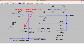
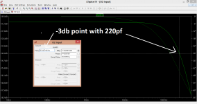
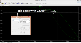
These show the effect of just the input filter on bandwidth with a 10k for R7. You can see that increasing the cap to even as high as 2200pf still has the -3db point above the audio band. So 10k and 220pf is fine.
These show the effect of just the input filter on bandwidth with a 10k for R7. You can see that increasing the cap to even as high as 2200pf still has the -3db point above the audio band. So 10k and 220pf is fine.
Attachments
Last edited:
Yes, keep R17 and R21
I might post a bit more on the subject of gain on the 02. There are different ways to reduce the gain, and some may give a much better result than others. Many opamps, although 'unity gain stable', offer better subjective performance when not used in this way. That is why I suggested increasing the input resistor as another possible solution.
I went and removed R19 and R23 and tested this last night and then test again with 1.5k resistors to give me 2x, a touch lower than the 2.5x. At 2x, and listening to different genres and recordings, that setting seemed to okay for now although I never needed to go past 12 o'clock. Will leave at this setting for the time.
The Input Stage In The Real World.
I happened to have some NJM2068 opamps (the single in line or S.I.L.) variety and thought a real test of how it all behaves would be good.
The input frequency for this was 50kHz and the input voltage adjusted for each gain change such that the output was always a nominal 6 volts pk/pk. The caps I used were 150pf rather than 220pf. The effect of this is to make the tests of higher input impedance seem a little better than they would be with 220pf. Not a huge difference though.
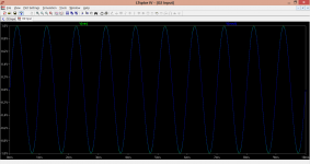
The standard input stage with 1k (R17) feedback return (the low gain setting)

Next I tried the unity gain configurations. First the easy approach which just sees the lower feedback return resistor (R17) removed and then in the second picture, the effect of shorting out the 1.5k feedback return (R16).
Simple unity gain configuration You can see the slight peaking which is the effect I mentioned earlier but in reality its not bad at all, in fact better than I thought it would be.

Conventional unity gain with feedback resistor R16 shorted This shows a slight reduction in that peaking but the difference was small.

Now we change the input resistor (R7) to create an input attenuation network while retaining the standard low gain feedback network.
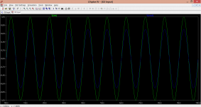
10k Input resistor This shows the effect of the 10k plus 220pf coming into play. The rise and fall times are now increased as the filter network has more of an effect.

22k Input resistor The effect on the rise and fall times is now even more pronounced however as we calculated earlier, it is still perfectly acceptable and in many ways no bad thing. It filters hf hash and noise on the input.

22k and reducing the 220pf input cap to 47pf This shows the dramatic effect of the cap on the hf response. The rise and fall times are now faster implying extended hf response however that may not be the 'best' combination. I suspect some middle ground would be optimum, perhaps 82 or 100pf for the 22k. There are no hard and fast rules, no right and wrong.

I happened to have some NJM2068 opamps (the single in line or S.I.L.) variety and thought a real test of how it all behaves would be good.
The input frequency for this was 50kHz and the input voltage adjusted for each gain change such that the output was always a nominal 6 volts pk/pk. The caps I used were 150pf rather than 220pf. The effect of this is to make the tests of higher input impedance seem a little better than they would be with 220pf. Not a huge difference though.
The standard input stage with 1k (R17) feedback return (the low gain setting)
Next I tried the unity gain configurations. First the easy approach which just sees the lower feedback return resistor (R17) removed and then in the second picture, the effect of shorting out the 1.5k feedback return (R16).
Simple unity gain configuration You can see the slight peaking which is the effect I mentioned earlier but in reality its not bad at all, in fact better than I thought it would be.
Conventional unity gain with feedback resistor R16 shorted This shows a slight reduction in that peaking but the difference was small.
Now we change the input resistor (R7) to create an input attenuation network while retaining the standard low gain feedback network.
10k Input resistor This shows the effect of the 10k plus 220pf coming into play. The rise and fall times are now increased as the filter network has more of an effect.
22k Input resistor The effect on the rise and fall times is now even more pronounced however as we calculated earlier, it is still perfectly acceptable and in many ways no bad thing. It filters hf hash and noise on the input.
22k and reducing the 220pf input cap to 47pf This shows the dramatic effect of the cap on the hf response. The rise and fall times are now faster implying extended hf response however that may not be the 'best' combination. I suspect some middle ground would be optimum, perhaps 82 or 100pf for the 22k. There are no hard and fast rules, no right and wrong.
Hello.
After a long time of use, my O2, has developed a problem.
I unplugged the power while the batteries were inside, and music was playing; that resulted in a *POP*.
Long story short, it has stopped working on the battery supply, yet it is still working on the AC.
What do you gather the cause might be? (there was no short circuit)
I am going to diagnose it soon to determine whether one of the MOSFETS are to blame or the comparator is.
Edit: All of the voltages on U2 check out. (On the AC)
Last edited:
Strange symptoms. Let us know what you find.What do you gather the cause might be?
Make certain the batteries are good, and fully charged. And test D2 & D6.
Everything else is common to the AC and battery, or is AC only.
D2 and D6 are working.Strange symptoms. Let us know what you find.
Make certain the batteries are good, and fully charged. And test D2 & D6.
Everything else is common to the AC and battery, or is AC only.
The batteries seem to be fine.
When running on battery power, all of the voltages at U2 are positive, so are the voltages at both + and - terminals.
I will try swapping the comparator just to be sure it's not Q1/Q2; as I have no idea how to diagnose a comparator unit.
- Home
- Amplifiers
- Headphone Systems
- The Objective2 (O2) Headphone Amp DIY Project