As a mention, I do plan on using the stock transistors, no way I'm using tip41. Just that I didn't want the original ones hurt until everything works as it should.
Actually I already talked to someone to help me source the original ones in case I do mess up while finishing this project.
Actually I already talked to someone to help me source the original ones in case I do mess up while finishing this project.
Looking at the schematic, it looks like it will "operate" without output transistors. That is, run into a high impedance load - say around 2k ohms. You could check that it's not distorting, has low offset (or proper quiescent voltage on the hot side of the output cap), and the proper 0.5-0.6 ish volts across the Rbe's (R749, 751, etc.). When you're satisfied then install the output transitors. This is normal procedure for servicing big monsters like the old Flame Linears.
I'll bet good money the TIP41's would work just fine in that circuit. There's just nothing finicky about it - it's not like they've got a super high loop gain or anything tricky with the biasing. Output transistor gain and speed has very little to do with it unless you're at the extremes, less than 1MHz on the low end or over 50 MHz on the high end. Jap audio outputs from that vintage are pretty much all between a few MHz and about 20. For designs like this, cost and availability were the drivers for what to use. Many TIP41's have very high gain at small signal (a few mA to 10's of mA), but they all fall like a stone to around 20 at rated 6A. I'd prefer to keep TO-66's in there for that vintage look. But if I had to replace a dead set, I'd even think about shoehorning in some TO-247's (TIP35 or similar) because that would make it bulletproof.
I'll bet good money the TIP41's would work just fine in that circuit. There's just nothing finicky about it - it's not like they've got a super high loop gain or anything tricky with the biasing. Output transistor gain and speed has very little to do with it unless you're at the extremes, less than 1MHz on the low end or over 50 MHz on the high end. Jap audio outputs from that vintage are pretty much all between a few MHz and about 20. For designs like this, cost and availability were the drivers for what to use. Many TIP41's have very high gain at small signal (a few mA to 10's of mA), but they all fall like a stone to around 20 at rated 6A. I'd prefer to keep TO-66's in there for that vintage look. But if I had to replace a dead set, I'd even think about shoehorning in some TO-247's (TIP35 or similar) because that would make it bulletproof.
How would I connect the high load instead of the output transistors? I leave the 2SD315 collector unconnected and put it between base/emitter?
I just got the 200 KSC1845/KSA992 pairs and I need to match them.
I usually used two schematics on my breadboard, the simpler one allowed me to test for leakage as well.
But now I'm interested to test them at their working conditions in the buffer/preamp.
What would be better from these two schematics? Or how could I adapt them to get them to test the transistors closer to their working condition.
Attachments
Yes, H701 is a phase splitter. It gives two identical signals (but 180 degrees out of phase), one from the emitter and one from the collector.
I think what wg_ski means is that you could remove the output transistors completely and that the amp would power up normally to allow a check on the DC conditions. You mustn't connect any speakers though. Its a trick I often use. You may or may not need something like the 2k loading which would just take the place of a speaker.
I think what wg_ski means is that you could remove the output transistors completely and that the amp would power up normally to allow a check on the DC conditions. You mustn't connect any speakers though. Its a trick I often use. You may or may not need something like the 2k loading which would just take the place of a speaker.
There are lots of ways of matching transistors. The first circuit allows you to test NPN and PNP. The second would need the battery reversing for NPN's and you might need to alter the resistor values too.
The second I'd just reverse the power leads and meter leads for NPN.
How would I connect the high load instead of the output transistors? I leave the 2SD315 collector unconnected and put it between base/emitter?
You would leave them out entirely. The amplifier will be capable of driving a few k ohms down to perhaps a few hundred (from the speaker terminal or headphone jack). Just not a speaker, and be careful not to short the output as it could take out the drivers. Fortunately they are cheap and a lot of things will work in their place if you do screw up.
Ok, I got the ceramic caps as well and I managed to match and install the rest of small signal transistors.
To put my mind at ease I'd like to replace the last small signal transistors.
For 2SC1318 I will use 2n4401. I will bend the leads as 2n4401 is ebc not ecb.
The last type is the 2SC1384 transistor. It is a TO-92L case. And it's coupled to the thermistor or whatever it's called. Looks like a diode in the datasheet but it conducts both ways, dependent on temperature off-course.
Now there are some comparable transistors that I could easily source but they are another kind of case. I guess the circuit and parts are selected in accordance with the thermal characteristics of the TO-92L case of 2SC1384.
But maybe it's not so critical. I don't know. What do you say? 2sc1384 is kind of scarce. I found some UTC copy of this transistor but I don't trust it.
This is the datasheet:
http://lib.chipdip.ru/249/DOC000249945.pdf
The longcase TO92 transistors On Semi sells, have a higher watt rating than regular TO92. For example the MPSW55/56 which is a 1 watt part with 50 degC/watt thermal resistance to case. On says the US name for this case is TO226AE.
Cut up a dead PCAT power supply: many of those are chock full of long case TO92parts.
Cut up a dead PCAT power supply: many of those are chock full of long case TO92parts.
The longcase TO92 transistors On Semi sells, have a higher watt rating than regular TO92. For example the MPSW55/56 which is a 1 watt part with 50 degC/watt thermal resistance to case. On says the US name for this case is TO226AE.
Cut up a dead PCAT power supply: many of those are chock full of long case TO92parts.
Thank you for the tip. But will any npn to92L do?
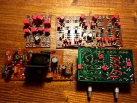
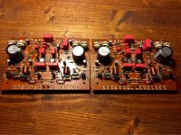
I managed to finish replacing parts. All boards done and ready for install (if I don't replace to92l transistors).
Hope I have time tomorrow night to make some progress, but this weekend we should learn if it blows or sings

I would suggest the originals are probably better matched to the duty than anything you can buy. That is if you didn't damage them taking them off. The PCAT transistors are "switcher" transistors, not "amp" transistors. And I'm finding modern amp transistors have much larger gains than old ones, which is causing me to redesign the circuit in the 1966 design amp I am trying to repair. The new transistors either saturate or go full Vcc, I can't get my VAS to stay in the linear zone of about half Vcc over the range of possible temperatures.
It works! Sort of...  )
)
First I fired it up with the lightbulb, it stayed dim so then I knew nothing is going to blow.
Then I removed the lightbulb, checked the power supply and adjusted for 35V. Then adjusted the bias on all boards at 15mA. So far so good.
Then I connected the output of my computer (after checking there's no DC on the jack) to the amp and yes! Music! Sounds awesome so far! I tested with some crappy headphones at first. I set the back switch to 4x12 so I can listen to each channel individually. The front channels are working good. When I switched the headphones jack to the rear channels that's when I noticed the sound is dim, can hear it but it's got no power.
Surely one of the two amps isn't working, or somewhere in the preamp section there's something happening. Weird enough, I could set the bias on all 4 channels.
Will be back with updates.
Interesting, I just saw that on headphones connector each channel comes from a different board. So I can draw the conclusion that both output boards should be working.
Forgot to mention that the headphone signal comes from the output of each output board via a resistor divider.
So this leaves me to believe the issue lies somewhere on the low signal boards.
So, oscilloscope time!
Forgot to mention that the headphone signal comes from the output of each output board via a resistor divider.
So this leaves me to believe the issue lies somewhere on the low signal boards.
So, oscilloscope time!
Attachments
Boy, do I feel stupid 
In fact I've done a good job and it works! The problem I was having was due to the fact that having taken the faceplate off I couldn't really tell where each knob was set at so the Mode switch was in Discrete Mode (I think) rather than in 2ch mode.
Now I set it correctly and all 4 channels work as they should
I might as well set the clipping since I have my oscilloscope out now.
In fact I've done a good job and it works! The problem I was having was due to the fact that having taken the faceplate off I couldn't really tell where each knob was set at so the Mode switch was in Discrete Mode (I think) rather than in 2ch mode.
Now I set it correctly and all 4 channels work as they should

I might as well set the clipping since I have my oscilloscope out now.
- Status
- This old topic is closed. If you want to reopen this topic, contact a moderator using the "Report Post" button.
- Home
- Amplifiers
- Solid State
- to92 transistor replacement


