Acko,
I cannot get I2C communications to work with an Arduino Uno. The same Arduino will work with a BIII. I used the correct I2C address for the ADC, but I get no data returned from the ADC.
Is there anything special about I2C with the ADC verses the DAC from ESS?
John
John, The ADC module is supplied with factory default settings for Hardware mode - see page #8 of the AKA102B manual. There are solder pads marked 'A', 'B, 'C' and 'D'. Pads 'C' and 'D' also connects to I2C lines SDA and SCL respectively but 'D' is tied low, 'C' is tied high for hardware mode. For software mode using I2C, both 'C' and 'D' needs to be tied high (Vdd)
What you should do now to enable I2C comms is to remove the '0' link from 'D' and then bridge the '1' link instead. No change for 'C'. This will enable the correct pull-ups for the SCL and SDA lines -see schema for more details. Also, please note the I2C is 3.3V type and make sure your external controller like Arduino matches this level. 5V I2C signals may damage the ADC module. Thought Arduino is 5V system, so please take care!
Last edited:
John's question lead me to ask if I can use my Acko Dac controller to program permanently the ADC to output 24 bit?
//
Yes, you can use the AKC12 controller and issue register commands directly from host PC via serial port but the firmware on the AKC12 looks for 9018 DAC during boot and will not proceed if DAC is not connected (will be flashing red). So you will need to tether it to your DAC at least during boot stage.
I can do a stripped down version of this controller for this ADC if other options are not favourable.
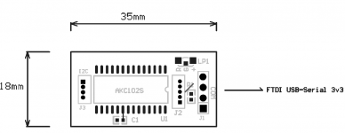
ADC Controller
Something like this:
Basically a general purpose USB-I2C converter. Connect to host PC, run a terminal emulator software like Win Hyperterminal and issue register commands to any connected I2C device.
Not sure if there is anything similar off-the-shelf?
I can do a stripped down version of this controller for this ADC if other options are not favourable.
Something like this:
Basically a general purpose USB-I2C converter. Connect to host PC, run a terminal emulator software like Win Hyperterminal and issue register commands to any connected I2C device.
Not sure if there is anything similar off-the-shelf?
Attachments
That board looks interesting.
Is this one usable?
Adapter Plate IIC I2C TWI SP Modulo Serial Interface Board Porta Arduino 1602LCD | eBay
Level discussion above...
IIC I2C Interface Level Conversion Module 5 3V System for Arduino Sensor | eBay
//
Is this one usable?
Adapter Plate IIC I2C TWI SP Modulo Serial Interface Board Porta Arduino 1602LCD | eBay
Level discussion above...
IIC I2C Interface Level Conversion Module 5 3V System for Arduino Sensor | eBay
//
Acko,
Thanks for your response.
I used an Arduino board that has 3.3v outputs. I also made the modification so both lines had the pullup resistors connected. I think I did not make my question clear concerning the DAC. I only meant to say that the controller I was using does work with ESS chips.
Here is what I get when I try use the Arduino. The program will hang if the ADC chip is not powered. If the chip is powered the program runs but returns the default value. The code I used was taken from HiFiduino's 9018 code. I did change the chip address to 0x4A.
byte readRegister(byte regAddr) {
Wire.beginTransmission(0x4A);
Wire.write(regAddr);
Wire.endTransmission();
Wire.requestFrom(0x4A,1);
wire.endTransmission()
if(Wire.available())
return Wire.read();
else
return 0;
}
That board looks interesting.
Is this one usable?
//
Hm,, probably not. How about this one then?
FTDI UMFT201XB 01 Dev Module Mini USB B to I2C | eBay
//
Acko,
Thanks for your response.
I used an Arduino board that has 3.3v outputs. I also made the modification so both lines had the pullup resistors connected. I think I did not make my question clear concerning the DAC. I only meant to say that the controller I was using does work with ESS chips.
Here is what I get when I try use the Arduino. The program will hang if the ADC chip is not powered. If the chip is powered the program runs but returns the default value. The code I used was taken from HiFiduino's 9018 code. I did change the chip address to 0x4A.
byte readRegister(byte regAddr) {
Wire.beginTransmission(0x4A);
Wire.write(regAddr);
Wire.endTransmission();
Wire.requestFrom(0x4A,1);
wire.endTransmission()
if(Wire.available())
return Wire.read();
else
return 0;
}
I am not familiar with Arduino but I will test it out with my own controller AKC12 and see. BTW, module must be fully powered before attempting to communicate with it.
Also, if your external controller has pull-ups already then link pads 'C' and 'D' of the ADC module described earlier should have all links removed. Again see schema to make sense of this setup.
Hm,, probably not. How about this one then?
FTDI UMFT201XB 01 Dev Module Mini USB B to I2C | eBay
//
They all look suitable, just make sure they are 3.3V types. I found this also interesting :
USB-ISS 3v3 type Module by Robot Electronics UK
Acko,
Thanks for your response.
I used an Arduino board that has 3.3v outputs. I also made the modification so both lines had the pullup resistors connected. I think I did not make my question clear concerning the DAC. I only meant to say that the controller I was using does work with ESS chips.
Here is what I get when I try use the Arduino. The program will hang if the ADC chip is not powered. If the chip is powered the program runs but returns the default value. The code I used was taken from HiFiduino's 9018 code. I did change the chip address to 0x4A.
byte readRegister(byte regAddr) {
Wire.beginTransmission(0x4A);
Wire.write(regAddr);
Wire.endTransmission();
Wire.requestFrom(0x4A,1);
wire.endTransmission()
if(Wire.available())
return Wire.read();
else
return 0;
}
John, your chip address "0x4A" is wrong. Please refer to ESS datasheet for the correct chip address for 9102 ADC (RE: ADDR Pin=0/1") Page #24
Also, for the AKA102B module, use ADDR Pin =1 reference (as in the ESS Datasheet) as point 'B' on module is tied to high for "Hardware Mode' default.
If you wish to use ADDR Pin =0 then link pads marked "ADR0' (underneath the board)
Last edited:
They all look suitable, just make sure they are 3.3V types. I found this also interesting :
USB-ISS 3v3 type Module by Robot Electronics UK
The top one only does 5v for I2C?
//
The top one only does 5v for I2C?
//
Select this only USB-ISS - Enhanced USB-I2C Module (3.3V)
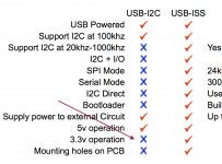
Function I2C ISS
3.3v operation X V
OK?
//
Looks like it is the case but please check the details before considering.
I will still go ahead with my own controller as this ADC chip has interrupt functions that can be very useful to indicate things like clip and lock conditions. So if you look at the I2C port of the AKA102B there is an extra line for interrupt signal. So interrupt-driven I2C comms as when needed instead of the constant polling type that just creates unnecessary switching noise.
Last edited:
")
Acko,
Still no go. I changed the address to 0x96. I2C in Arduino uses the 7 MSB's. This means the address is 0x4B. This usage is explained in HiFiDUINO's code for the 9018, which I have used on several 9018 chips with good results.
My current setup has only the SW pads shorted. All others are open. The Arduino has the needed pullup resistors in place for the I2C lines. Does the external clock have to hooked up?
Thanks for your help and patience.
John
Acko,
Ignore my last message. I got the I2C communication to work.
I did have to use the 0x96 address (0x4B on the Arduino). As stated above only the SW contacts are shorted, all other are open. I did not look at the schematic and see that the addr line was pulled up.
The chip does need the clock to start. I am using a USBStreamer. I removed the TOSLINK input and connected the SPDIF output from the ADC to the exposed input on the Streamer. The Streamer needs to be powered up and the clock set to SPDIF for the ADC to work.
Later today I will test the audio input.
Thanks again.
John
ADC update
I now have the ADC working. I could not get the USBStreamer to work with the SPDIF input. It may have been as simple as a bad connection. I decided to go to I2S. This works great.
I can change the sample rate for the ADC and this shows up in the Streamer control panel. The Arduino Buono works great, as it has the option for 3.3 volt operation.
I have not done any optimization for the audio chain. I ran my ARC Ref5 balanced outputs right into the ADC with no buffer. I used 3 meter long XLR cables made from Cat5 wire. I increased the output of the ARC until I clipped the ADC and then backed it down some. I used the Arduino to poll the clip register every second. Now I need to get the Arduino to react to the Interrupt line when clipping.
I am using Audacity for the recordings. I recorded some vinyl using 192khz at both 24 and 32 bit depth. I am surprised how good they sound with no optimization. It looks like I will be able to archive a lot of vinyl with this and be able to listen too it through my DAC. It will be interesting to see how my opinion of the sound quality holds up over time.
- Status
- This old topic is closed. If you want to reopen this topic, contact a moderator using the "Report Post" button.
- Home
- Source & Line
- Digital Line Level
- ADC using ES9102/9112