Hi, I am still trying to decide what to build, I have been reading a lot and ask a lot of questions. I learned a lot thanks to you guys. I think for SS amp, I have no choice but to layout my own pcb. This cost the major portion of money. This means I have to determine on a certain topology. With the topology, I can over design and put in all the bells and whistles, then jumper anything that I don't need. But if it is a wrong topology, then there is nothing I can do to change. This are the three topologies I am thinking That I read a lot of good things about.
1) Cordell's design with complementary LTP as IPS, symmetrical VAS. This seems to be the most common found in the majority of amps to different degree. I can put in complementary IPS with CCS as load and tail. Using Darlington VAS.
2) Apexaudio SR100/SR200 that doesn't use complementary IPS by I really like the way he implemented the symmetric drive VAS. There is a long thread on this and people seems to really like it. It's over 170 pages and counting!!! It must be very good!!!!
3) Then the whole CFA that is totally different.
I welcome suggestions of other topologies. So far, the three I listed above cannot be interchanged after I fab the pcb, so before I commit to pcb, I want to hear from you guys. As before, I only care about the sound, not the distortion number.
Thanks
Last edited:
Hi, I am still trying to decide what to build, I have been reading a lot and ask a lot of questions.
Hard choice, maybe you can put all the boards into one file and fab them all at once, then cut them apart when you receive them.
Hard choice, maybe you can put all the boards into one file and fab them all at once, then cut them apart when you receive them.
I did that with my guitar effect pedals because they are very small. But these are 4" X 8" minimum. I need two each minimum, likely 3 ea. That is more than one panel.
Problem is I absolutely have no idea about the sound. They are all circuits to me!!!!

How about walking before you run?
How about a bog standard 3-stage "Blameless" power amplifier:
Active device count = 18 transistors (if Output Power < 140W RMS / ch / 8 ohms)
Build a simple amplifier and learn. Once you have advanced to the next level, throw away the circuit board (which is the CHEAPEST part of the amplifier; the expensive parts are the transformer, chassis, and heatsinks). Make a new circuit board containing a fancier topology.
Repeat as desired.
How about a bog standard 3-stage "Blameless" power amplifier:
- LTP with current source and 3T current mirror: 6 transistors
- VAS with emitter follower input, current source load, and bias spreader: 4 transistors
- Triple Darlington output stage: 6 transistors (if Output Power < 70W RMS/ ch / 8ohms)
- Triple Darlington output stage: 8 transistors (if Output Power < 140W RMS/ ch / 8ohms)
Active device count = 18 transistors (if Output Power < 140W RMS / ch / 8 ohms)
Build a simple amplifier and learn. Once you have advanced to the next level, throw away the circuit board (which is the CHEAPEST part of the amplifier; the expensive parts are the transformer, chassis, and heatsinks). Make a new circuit board containing a fancier topology.
Repeat as desired.
I did that with my guitar effect pedals because they are very small. But these are 4" X 8" minimum. I need two each minimum, likely 3 ea.
That is more than one panel.Problem is I absolutely have no idea about the sound. They are all circuits to me!!!!
Part of the performance is in the layout and construction, so no one else knows either. I know that you just want to build one and use it,
but maybe you can build the chassis and power supply so any of them can be installed, and be able to try another circuit later on without
too much extra cost. The DIY Pass amps are often done that way.
Hard choice, maybe you can put all the boards into one file and fab them all at once, then cut them apart when you receive them.
Ha, maybe I should consider separate the OPS, put the power transistor and Vbe multiplier on one board so all the thermal matching stuffs on one smaller board. Then I can design different IPS and VAS on a separate board. If I match the location of the output of the top and bottom VAS to the input to the power board, I still can achieve point to point.
But this will require the layout that the IPS VAS on say the left side, and OPS on the right side. NPN on top of the power board and PNP on the bottom. That would put a lot of heat in a small area.
Part of the performance is in the layout and construction, so no one else knows either. I know that you just want to build one and use it,
but maybe you can build the chassis and power supply so any of them can be installed, and be able to try another circuit later on without
too much extra cost. The DIY Pass amps are often done that way.
Yes, I am going to get the chassis first and determine the location of the holes for the transistors, then I can make different circuits with the same mechanical location.
Ha, maybe I should consider separate the OPS, put the power transistor and Vbe multiplier on one board so all the thermal matching stuffs on one smaller board. Then I can design different IPS and VAS on a separate board. If I match the location of the output of the top and bottom VAS to the input to the power board, I still can achieve point to point. But this will require the layout that the IPS VAS on say the left side, and OPS on the right side. NPN on top of the power boardand PNP on the bottom. That would put a lot of heat in a small area.
Look at some of the Pass boards in the DIYaudio store for ideas. Just avoid "mirror image" style boards for left and right channels.
Instead think "dual mono" with identical boards and layouts for the two channels.
Last edited:
Ha, maybe I should consider separate the OPS, put the power transistor and Vbe multiplier on one board so all the thermal matching stuffs on one smaller board. Then I can design different IPS and VAS on a separate board. If I match the location of the output of the top and bottom VAS to the input to the power board, I still can achieve point to point.
But this will require the layout that the IPS VAS on say the left side, and OPS on the right side. NPN on top of the power board and PNP on the bottom. That would put a lot of heat in a small area.
It sounds like you're describing a Slewmaster. http://www.diyaudio.com/forums/solid-state/248105-slewmaster-cfa-vs-vfa-rumble.html
How about walking before you run?
How about a bog standard 3-stage "Blameless" power amplifier:
Active device count = 16 transistors (if Output Power < 70 W RMS / ch / 8ohms)
- LTP with current source and 3T current mirror: 6 transistors
- VAS with emitter follower input, current source load, and bias spreader: 4 transistors
- Triple Darlington output stage: 6 transistors (if Output Power < 70W RMS/ ch / 8ohms)
- Triple Darlington output stage: 8 transistors (if Output Power < 140W RMS/ ch / 8ohms)
Active device count = 18 transistors (if Output Power < 140W RMS / ch / 8 ohms)
Build a simple amplifier and learn. Once you have advanced to the next level, throw away the circuit board (which is the CHEAPEST part of the amplifier; the expensive parts are the transformer, chassis, and heatsinks). Make a new circuit board containing a fancier topology.
Repeat as desired.
I am new in audiophile, but I have years of experience in electronics, prototyping, pcb layout and building. I successfully designed and build two guitar amps that have channel switching, cascade gain channel and power scaling one time through the first time. If I nail the circuit topology, I have high confidence that I can layout and have it work as design one time through with a little tweak.
I plan to choose out the chassis, transformer and filter caps first, this is a question on pcb specifically.
Last edited:
It's hard to make a suggestion without bringing in personal bias (pun intended).
I always built Self type (Linn) amplifiers and was almost always pleasantly surprised. I saw the VSSA and it's variants and decided to try out the PeeCeeBee variant. I have since tried a few and can say I'm very fond of the vertically symmetrical CFA designs for their sound. Not that other types don't sound good, I've listened to some different basic architectures and have enjoyed most of them, but the 'less is more' concept is very pleasant to me. All very personal.
Consider a modular approach perhaps? Then you can bolt in design du jour and find what you like without anyone else's prejudices. The most expensive and laborious parts stay put and the input and gain section can be swapped out. Look to some of the ideas in the SlewMaster thread.
Thanks guys, I already feel better by just talk here. Modular approach is the way to go. Separate the OPS from the IPS and VAS. Then I have smaller boards and it's likely to be a lot cheaper. Bigger size limits how the fab house can layout onto their panel and result in waste. They can fit a 4" X 4" much easier.
I can build more small boards. I can even have two OPS board, one for BJT and one for MOSFET.
I guess it's worth getting a taller chassis so I get more vertical dimension so I can have a taller heat sink to get back the necessary area for heat dissipation.
I can build more small boards. I can even have two OPS board, one for BJT and one for MOSFET.
I guess it's worth getting a taller chassis so I get more vertical dimension so I can have a taller heat sink to get back the necessary area for heat dissipation.
Also, The OPS is the section have mechanical constrain because of the heat sink. With that separate out, I can even consider breadboarding the IPS and VAS on a copper plane board like RF breadboard. Nothing is expensive in the IPS and VAS, it can be throw away boards.
You guys give me good ideas just by talking!!!
Thanks
You guys give me good ideas just by talking!!!
Thanks
If you can keep input boards under 4" x 4" they are very cheap to have made.
Yes, I want to see whether I can fit the OPS board into 4" X 4"!!! 3 pairs of transistors wrap around.
CSH6
Hi Alan
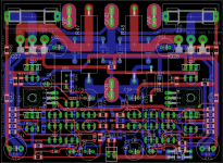
I just finished putting the finishing touches on my latest design - CSH6 - and sent the files to the board house this morning.
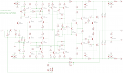
I've built a lot of Lin / Blameless in a myriad of configurations, some very simple SE and symmetrical current feedback designs, and wanted to try something a little different, and chose this time to base something around Bob Cordell's Figure 7.10 with a few touches of my own.
The challenge was squeezing the capability into a 3 x 4" board!
1) Cordell's design with complementary LTP as IPS, symmetrical VAS. This seems to be the most common found in the majority of amps to different degree. I can put in complementary IPS with CCS as load and tail. Using Darlington VAS.
Hi Alan
I just finished putting the finishing touches on my latest design - CSH6 - and sent the files to the board house this morning.
I've built a lot of Lin / Blameless in a myriad of configurations, some very simple SE and symmetrical current feedback designs, and wanted to try something a little different, and chose this time to base something around Bob Cordell's Figure 7.10 with a few touches of my own.
The challenge was squeezing the capability into a 3 x 4" board!
Attachments
Hi Alan
I just finished putting the finishing touches on my latest design - CSH6 - and sent the files to the board house this morning.
I've built a lot of Lin / Blameless in a myriad of configurations, some very simple SE and symmetrical current feedback designs, and wanted to try something a little different, and chose this time to base something around Bob Cordell's Figure 7.10 with a few touches of my own.
The challenge was squeezing the capability into a 3 x 4" board!
My plan is a little simpler, I am planning to use two EF OPS instead of 3EF like yours. I just use higher bias current in the VAS. I don't want to deal with oscillation problem of the 3EF. But I plan to have 3 complementary pair of power transistor. Other than that, it's very similar to yours.
- Status
- Not open for further replies.
- Home
- Amplifiers
- Solid State
- Help on deciding the topology of the design.