Thank you Andrew
Now you made it perfectly clear to me.
I will revert to the "usual" 4 poles and avoid all the trouble.
And I will build the Quasimodo thing for learning purposes")
Now you made it perfectly clear to me.
I will revert to the "usual" 4 poles and avoid all the trouble.
And I will build the Quasimodo thing for learning purposes
Low esr is the opposite of resistance in the capacitor.
A circuit that is suscpetible to ringing needs RESISTANCE to absorb the energy in the initial pulse and subsequent ringing.
Miss out the resistance and the oscillation remains either undamped, or lightly damped.
A normal esr electrolytic smoothing capacitor has enough resistance to not ring on it's own.
Adding another capacitor and some cable/wire/leadout/trace inductance creates a 2pole circuit that is susceptible to oscillation.
Getting the damping resistor wrong is the BIGGEST mistake one can make. Adding a low esr capacitor is exactly that same mistake.
One needs to add a high esr capacitor where it is needed. And this is not usually on the remote located PSU, but at the amplifier circuit.
The PSU may not ring when hit with disturbing pulses. It would not need a damping resistor.
A PSU that does ring when hit with disturbing pulses must have a damping resistor added.
Quasimodo is a tool to let you measure the optimum resistor value for a ringing system.
Q4x gone, rest of semis regulator are OK
Ahh, so Q3x was pulling current through the base of bad Q4x, that explains why so little current through R3x.
Measured now R3X and is 9K1
Q3X is between 3.09-3.28mA
Use 11K R3x.
It's not bugging me, I was just curious to see what changes I could hear as it warmed up, and though others might find it interesting too. I was actually very pleased that it got as good as it did so quickly -- as you say, an hour or so warm-up is not unusual. Since I had measured the current through the source resistors when fairly cold, I was surprised by the apparent small change in gain, although of course I have no numbers to back up that impression. It just seemed a little louder after twenty or thirty minutes.
The CCS is intriguing, but as you said before introduces some noise, which in a high-gain configuration is probably not a good idea. As for RF, I'm not too worried about it. It was very faint, inaudible from any distance away. I suspect my rewiring job on the tonearm is to blame -- I gently twisted the tonearm wire pairs and ran them all the way to RCA's on the TT chassis. If I ever get around to replacing that part with some nice flexible shielded cable I bet that will make a difference.
The voltage across the first stage's load resistor R4 falls in reality when you see TP1-TP1 climbing during warm up. So it starts above center and gradually centers between Vpk-Vpk max. I.e. there is bias from the get go.
20mins ain't something too long in a context of a whole system settling for temp vs. best sound IMO, it usually takes an hour especially with richly biased power amps or any vacuum tubes in the chain.
If it still bugs you, there is the active CCS path to follow. Not that complex a modification (for MC,LMC versions ONLY. MM,HMC do not care due to good Tempco high R2 control):
Use a Supertex DN2540 (TO-220 version) set it at 18mA for two 369s. Needs two resistors, one gate stopper 470R & one to find its exact value that programs IDSS on a breadboard 20VDC test for each different Vgs(OFF) DNMOS sample. A 100R trimmer in rheostat mode may help you define it. Make those three parts into a two legged in-out thing and solder it upright substituting R13. Revisit TP1-TP2 setting. Then the 369s will have the designed bias irrelevant to their positive Tempco from the moment you flick the "ON" switch. DNMOS give their own hiss contribution but you can judge if it will be audible in your system context and phono gain.
If you got RFI ingress in your installation, you can either use: A. Ferrite bead usually in a place like input cable PCB side hot, 369s gate legs. B. 1uH inductor in series with signal to a high impedance point (looks like a resistor). C. 10nF cap from input RCA ring direct to chassis within very short distance.
*All the discussed above solutions from active CCS bias to signal RFI countermeasures are additions that may prove also audible for the better or worse.
Hi Salas, I'm building a balanced one with one 369 for 56 dB gain and I'm intrigued by the possibility to use a CCS in R13 position. You suggest a Supertex DN2540 ( ...and I get a lot of them), but I have a single 369 and I need only 9mA, not 18. Can I use a K170 with the same Idss , tying G and S and connect it in the R13 position? IMHO ccs bring always a great sense of air and musicality over the simple resistor polarisation... and remain a simplistic thing.
Hi Salas, I'm building a balanced one with one 369 for 56 dB gain and I'm intrigued by the possibility to use a CCS in R13 position. You suggest a Supertex DN2540 ( ...and I get a lot of them), but I have a single 369 and I need only 9mA, not 18. Can I use a K170 with the same Idss , tying G and S and connect it in the R13 position? IMHO ccs bring always a great sense of air and musicality over the simple resistor polarisation... and remain a simplistic thing.
If it can handle the dissipation in the long term (there will be high VDS), maybe use a TO-92 sink, you can try it. It will inject some own noise too but you may not object. The Supertex is not doing a good job if asked for less than about 20mA anyway.
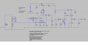
Been simulating the R3 Mod with the Supertex depletion mode mosfet and found that with a CCS instead of R3, VR1 trimmer action is irrelevant.
Once we find the correct CCS current as to bias the folded half way, trimming R12 only changes Vds in the DNMOS..... It might change something sonically but does nothing in biasing terms.
Maybe we could also do without C6 if using the ccs ...?
Once we find the correct CCS current as to bias the folded half way, trimming R12 only changes Vds in the DNMOS..... It might change something sonically but does nothing in biasing terms.
Maybe we could also do without C6 if using the ccs ...?
Attachments
- Home
- Source & Line
- Analogue Source
- Simplistic NJFET RIAA