I stumbled across a warehouse sale that had a collection of some of the nicest antique furniture I have ever seen. Complete sets from 1800's doctors and dentists offices, in pristine original condition. In the corner, I saw an amp that jumped out as not being like the other items. I pulled the top cover off and saw that a channel was blown. Seller gave me his bottom dollar price - take it or leave it. I left to think about it and Googled it. That's when I discovered this forum and began to understand why the seller thought so highly of an old fried amplifier. I bought it with hopes of having something rare and fine, that was crafted by a master, not off an assembly line in a sweat shop.
A year later after combing the internet in my spare time, buying up gobs of components from surplus store (99% of which do me no good), and scrounging up test equipment opportunistically (repairing it), reading books, . . . I have reached a point where this feller needs to get back together. I have been unable to find one schematic that fits what I have, but it seems to have blocks from CAS1, 400/4000, Stasis 2, along with being what seems to be previous repairs. My mission has been to restore it. Unless advised otherwise, I've overcome the initial desire to keep it "all original," however, I would like to get it back to the "original recipe" of the Chief Chef. The thin slices of time I have to work on it, would push completion out to 2018 by the time I figure out the math and nuances of components.
I have deliberated over how to implement circuit blocks used in subsequent designs, (coupling and bias circuitry) but lack the time to allocate to reinventing this wheel, and recognize that the day will never come that I will "know better" than Nelson himself, Zen, even Jon Soderberg, or other noteworthy techs that participate in this forum.
There is a small black sticker on the rail with "Cathy" hand scribed on it. Was that customer or a Threshold assembler?
Please know that I treasure your advise in helping me get this back in action as a fledgling audiophile and admittedly dangerous electronics technician.
Justin in Denver
I have replaced several output 2n5876/8's, and made a cursory effort to match Hfe on them, group together, and remount - torqued, with corning compound/mica, and polishing plate with 1800 grit on 5" orbital sander endeavoring to maximize thermal conductivity.
I have new Dale NS-28 1R0 2w emitter resistors, use them or stick with carbon comp?
On FEb, where does resistor type matter? I have a healthy collection of hi end resistors that I bought from a surplus store with aerospace quality stuff, need to review datasheets, but suspect there are components better left with original carbon comp, than replacing with "something better" bearing a trivial characteristic that spoils the soup. One example is resistors with nice gold leads, if they are of the wrong construction. . . inductive, . . . where does that matter? It seems to matter in some areas . . . but cannot confidently apply to this circuit. Another example is the glass caps. I found one I bought in a bag of components for $15, on ebay for $750. The others are of relatively high dollar compared to many alternatives, but learned they don't play nicely with entire audio frequency range. I know these topics have been discussed in various threads, but not definitively nor by those of known competency. (No offense to anyone, though I have searched and read, I may have failed in my efforts to fairly recognize.)
Are there any books available on audio design that would help without sifting through 100 pages of differential equations and calculus? One that addresses different component compositions of passive components and ideal applications? I have books and white letters from internet that espouse the wonders of Polystyrene. Is a 5% tolerance styrene cap and improvement over a 2% silvered mica? I presume that tolerances and "matching" are of benefit when complementing another component in that circuit, but snubbers? For example, in this circuit, it seems that the .001uf film caps near collector/base of FT317/417's would benefit if they as equal as possible. If I had a pile of caps with 10% tolerance and found 2 that were closest, is that better than buying 2 new ones that are 1% tolerance? Is the tolerance based on their measured variation off the assembly line, or does a tolerance assigned mean that is the possible variation during use?
Soooo much to know, so little time.
Great find, but junk - No comprendo
I feared this would be your response. However, my neighbor has a 65 Mustang which I think is a heap of crap and waste of money. Because I haven't explained that to him, he takes great pride in it and his family enjoys it immensely. They are ignorant to the realm street rods I am family with, . . . ignorance is bliss. In the world of Pure Audio, I trust you are correct, but don't know the difference and many of my friends won't either, it is . . . a rough sketch from Rembrandt, not his masterpiece, but not without value.
OPLDF - no comprendo
what is your level of electronic expertise
As a Marine, they sent me to Avionics Technicians Course in Millington, TN. 20+ years ago, they spent a year full-time training me to be a electronics tech, then sent me to work on aircraft where we troubleshot to assemblies. I have a good general understanding, but a little dusty and shy on practical circuit board experience. Have a healthy reference library and can figure any one thing out, but far short of precision design. I can "repair" ANYTHING worth repairing, eventually.
Soldering, work in process. I have a weller 50w variable iron, Plato Vac Desoldering, and a bunch of random irons. I haven't quite nailed the perfect shinny joint, have a wide range of solders, fluxes, and chemicals out the wazoo. Opinions vary as to use lead, lead free, silver bearing, what to clean with, temperatures, . . . I suspect with specific guiddance, I could deliver.
working with DMM - Have many, fluke, snap-on, simpson, greenlee, other flukes, Tektroniks 2215, Leader 4 channel, basic transistor testors, capacitance meters, 22amp varistat, I'm a savvy accumulator
Brushes - yup
benzine - isn't that in Xylene? Have to go check labels, but if a specific chemical is needed, 99% chance I already have it in some form.
alcohol Isopropyl, denatured/ethyl,
solvents -Like Trichloroethylene , ferric chloride. . . .?
few general thoughts about your soooo nice project ;
-desolder and unmount ,-one by one- , all semis ; check , clean , clean their mounting position , put new thermal grease and mica if they are in position ; re-goo/re-mica all outputs as must !!
-doing that , with benzine or alcohol and distilled watter clean old and new flux residue , burns , clean & repair damaged traces
-decipher wattage of resistors ; replace carbon ones with generic** metal films (up to 600mW) and MOX (Pana 3W is what Papa use now, for emiter resistors and other power positions) ; your Dale if wattage is appropriate .
-silver mica , if Papa put it in some position , is still best choice for exact position
-poly-yadayada ; polycarbonate (MKC , as coded by Philips) is my fave ; that one is best bang for the buck as signal or signal cap bypass
-elko-yadayada ; Elna Silmic ; if signal one bypass with - MKC , what else
-when you're able to measure/match , tolerance range marked on cap is pretty irrelevant , isn't it ?
-books ; they're good as authors are ; there are many great engineers around , some of them wrote the book(s) ; in best of them you'll find least amount of two opposite things :audiophoolery ...... and blindness
**Vishay Beyschlag ; proper industrial quality , for ppl thinking that circuit is what's singing 99% , and last 1% is for parts ;same approach for caps - good industrial quality is what's worth greenies paid for
Great find, but junk - No comprendo .....
from rest of your reply , it's evident that you're there in adequate and comfortable .... slippers ; boots are too cumbersome
")
regarding no comprendo , there are many adequate sissy things , worth only of sending to Official Pass Labs Disposal Facility , situated in my back yard , where else ?

-desolder and unmount ,-one by one- , all semis ; check , clean , clean their mounting position , put new thermal grease and mica if they are in position ;
re-goo/re-mica all outputs as must !!
DONE
-decipher wattage of resistors ; replace carbon ones with generic** metal films (up to 600mW) and MOX (Pana 3W is what Papa use now, for emiter resistors and other power positions) ; your Dale if wattage is appropriate .
Trivial as this may seem to you, this guidance saves little people like me volumes.
-silver mica , if Papa put it in some position , is still best choice for exact position
Which is why I included a crude schematic and photos, . . . I don't know what he put there versus someone trying to get it off the bench and get paid. Like 47 ohm resistors below MPS6571's, not like that in any schematics. The missing 100K ohm resistors off of the 3440/5415's, before FT317/417. Haven't seen any schemes with dual FT's, missing pair 1n914's above bias circuit. There's a good handful of variations, I don't if that was done to dial in this thing to begin with, or was modified because someone since didn't know or didn't have the right thing.
-poly-yadayada ; polycarbonate (MKC , as coded by Philips) is my fave ; that one is best bang for the buck as signal or signal cap bypass
Right, thanks, just wanted your opinion because it's yours. I don't want to read the whole internet and don't think much of 99% of opinions.
-elko-yadayada ; Elna Silmic ; if signal one bypass with - MKC , what else
Bought Silmic based on your advice somewhere in forum. But, if bypassing, with MKC, . . . ? (where I need translation to save me a week of reading) Like the 47 & 220 uf in signal path - Put a ____ uf same voltage "MKC," in parallel through same PC holes?
-when you're able to measure/match , tolerance range marked on cap is pretty irrelevant , isn't it ?
Frankly, that's something I don't know. Is measuring the capacitance with meter and putting same values together sufficiently 'matching,' or does it need to be done with a signal at different temps? I really don't know. Is that all the tolerance is on a component, based on how it measures with simple meter when it pops off the production line, or if there is more to it?
-books ; they're good as authors are ; there are many great engineers around , some of them wrote the book(s) ; in best of them you'll find least amount of two opposite things :audiophoolery ...... and blindness
Correct, and it will take me 20 years to figure out which is which. With great respect for your opinions based on experience, whether you knew of any that told it simple and straight, and weren't lobbying for some crap agenda.
**Vishay Beyschlag ; proper industrial quality , for ppl thinking that circuit is what's singing 99% , and last 1% is for parts ;same approach for caps - good industrial quality is what's worth greenies paid for
Right, I have an obscene collection of tools by any standard, a machine shop, wood working, construction equipment. . . There have been times when I have used a Snap-on Combination wrench to remove bolts that Craftsman tools broke trying. The difference is real and it is quality, for a price. 98% of the time, craftsman does the job and the bolt doesn't know the difference. Then there's Harbor Freight tools that work 42.3% of the time, acceptable for weird crap used infrequently. I realize the price of "quality" is a waste when it is overkill, and that some claim a level of quality that doesn't exist justifying the price.
When it comes to tools, I can instantly see and feel the difference, from experience. Experience I don't have with electronics, you do, and I appreciate it greatly, even amongst the mockery. Truly, Thanks
I just want this running in some respectable condition so I can then move on to more worthy audio projects.
Slippers . . .) I wish, not yet, I still wear boots daily.
re-goo/re-mica all outputs as must !!
DONE
-decipher wattage of resistors ; replace carbon ones with generic** metal films (up to 600mW) and MOX (Pana 3W is what Papa use now, for emiter resistors and other power positions) ; your Dale if wattage is appropriate .
Trivial as this may seem to you, this guidance saves little people like me volumes.
-silver mica , if Papa put it in some position , is still best choice for exact position
Which is why I included a crude schematic and photos, . . . I don't know what he put there versus someone trying to get it off the bench and get paid. Like 47 ohm resistors below MPS6571's, not like that in any schematics. The missing 100K ohm resistors off of the 3440/5415's, before FT317/417. Haven't seen any schemes with dual FT's, missing pair 1n914's above bias circuit. There's a good handful of variations, I don't if that was done to dial in this thing to begin with, or was modified because someone since didn't know or didn't have the right thing.
-poly-yadayada ; polycarbonate (MKC , as coded by Philips) is my fave ; that one is best bang for the buck as signal or signal cap bypass
Right, thanks, just wanted your opinion because it's yours. I don't want to read the whole internet and don't think much of 99% of opinions.
-elko-yadayada ; Elna Silmic ; if signal one bypass with - MKC , what else
Bought Silmic based on your advice somewhere in forum. But, if bypassing, with MKC, . . . ? (where I need translation to save me a week of reading) Like the 47 & 220 uf in signal path - Put a ____ uf same voltage "MKC," in parallel through same PC holes?
-when you're able to measure/match , tolerance range marked on cap is pretty irrelevant , isn't it ?
Frankly, that's something I don't know. Is measuring the capacitance with meter and putting same values together sufficiently 'matching,' or does it need to be done with a signal at different temps? I really don't know. Is that all the tolerance is on a component, based on how it measures with simple meter when it pops off the production line, or if there is more to it?
-books ; they're good as authors are ; there are many great engineers around , some of them wrote the book(s) ; in best of them you'll find least amount of two opposite things :audiophoolery ...... and blindness
Correct, and it will take me 20 years to figure out which is which. With great respect for your opinions based on experience, whether you knew of any that told it simple and straight, and weren't lobbying for some crap agenda.
**Vishay Beyschlag ; proper industrial quality , for ppl thinking that circuit is what's singing 99% , and last 1% is for parts ;same approach for caps - good industrial quality is what's worth greenies paid for
Right, I have an obscene collection of tools by any standard, a machine shop, wood working, construction equipment. . . There have been times when I have used a Snap-on Combination wrench to remove bolts that Craftsman tools broke trying. The difference is real and it is quality, for a price. 98% of the time, craftsman does the job and the bolt doesn't know the difference. Then there's Harbor Freight tools that work 42.3% of the time, acceptable for weird crap used infrequently. I realize the price of "quality" is a waste when it is overkill, and that some claim a level of quality that doesn't exist justifying the price.
When it comes to tools, I can instantly see and feel the difference, from experience. Experience I don't have with electronics, you do, and I appreciate it greatly, even amongst the mockery. Truly, Thanks
I just want this running in some respectable condition so I can then move on to more worthy audio projects.
Slippers . . .
) I wish, not yet, I still wear boots daily.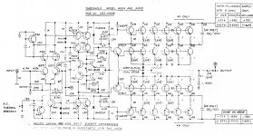
Nope, but thanks. I've scoured the internet fairly thoroughly looking for a match, without luck.
That's coupled only by resistors to 6571, doesn't have dual FT317/417's, is all A42/92's where this one is L01/51's, like several I have found it 'resembles' what I have, but isn't what I have.
That's coupled only by resistors to 6571, doesn't have dual FT317/417's, is all A42/92's where this one is L01/51's, like several I have found it 'resembles' what I have, but isn't what I have.
Grateful
That's the crux of the problem. It's not a simple question.
Look at the schematic of what I think I have (first post) and compare to these others. There are parts that have same component values and arrangement of components, but I haven't found a single scheme that is ~95%.
If a schematic exists (Nelson Pass' original design) I would just be silly with joy to have a road map to put this thing back together.
If not, Pass guidance to make it what it should be, unmolested by the lesser enlightened.
View attachment Threshold_400A.pdf

View attachment Threshold CAS1 schema redraw.pdf
That's the crux of the problem. It's not a simple question.
Look at the schematic of what I think I have (first post) and compare to these others. There are parts that have same component values and arrangement of components, but I haven't found a single scheme that is ~95%.
If a schematic exists (Nelson Pass' original design) I would just be silly with joy to have a road map to put this thing back together.
If not, Pass guidance to make it what it should be, unmolested by the lesser enlightened.
View attachment Threshold_400A.pdf
View attachment Threshold CAS1 schema redraw.pdf
Simple question-ish: What's that 68ohm resistor between emitter and base of 2nd o/p TO-3?
It's on scheme and visible in photo of rail, I think I even put a highlighted yellow arrow to it.
I saw it in a photo of another random 4000 rail posted online, so it's not a compete rogue, but . . . no comprendo.
Here:
It's on scheme and visible in photo of rail, I think I even put a highlighted yellow arrow to it.
I saw it in a photo of another random 4000 rail posted online, so it's not a compete rogue, but . . . no comprendo.
Here:
Last edited:
Simple question-ish: What's that 68ohm resistor between emitter and base of 2nd o/p TO-3?
It's on scheme and visible in photo of rail, I think I even put a highlighted yellow arrow to it.
I saw it in a photo of another random 4000 rail posted online, so it's not a compete rogue, but . . . no comprendo.
say loading ; to pre-load FT317 , so variation of base currents (sum of all upper outputs bases) is diminished

Input emitter resistors, I've seen 47r & 33r, to form a voltage divider.
Plausibly necessary . . ? But I really don't know, just speculation after a year of a 6th grader looking at the pictures in a college textbook.
not voltage divider
google emiter or source degeneration
feel free to read about cathode degeneration , too
Tant's are long gone.
Some circuits only have resistors between input and 6571. Some have both res & cap. Should I nix the 47uf coupling cap, and up the 220uf to 470?
Here is a rendition for conjecture: View attachment 457823
input cap or no ...... I always toss them , if possible
series input resistor - variations in value pretty much irrelevant
220p or 390p - leave what's in it , pretty academic difference , exact value can be tweaked with full set of signal generator and oscilloscope
390R or 820R? - defining gain of stage ; leave it as in majority of schm , if you can't decide , start with 820
next .....
- Status
- This old topic is closed. If you want to reopen this topic, contact a moderator using the "Report Post" button.
- Home
- Amplifiers
- Pass Labs
- Crispy or Original Recipe?