Ah, the real smoothdancer.Seasons greeting to you too.
Oh no,,,there is only one smooth dancer. He he,,
A merry Christmas to all of you helpful guys in here.
( love the dddac so far ).
DAC design and breakdancing! Power couple there.
Merry Christmas back Doede and to the rest of you!
My 4 stack boards are complete. I need to get them in the chassis, perhaps over the holidays. I gave up my wood shop in a move a couple of years ago, so drilling the holes is more difficult.
Merry Christmas back Doede and to the rest of you!
My 4 stack boards are complete. I need to get them in the chassis, perhaps over the holidays. I gave up my wood shop in a move a couple of years ago, so drilling the holes is more difficult.
Hi All,
After getting tired of waiting for the botic cape on bbb, I decided to try the Acko S03 pcb.
I just finished this board before the christmas holidays; I am afraid my family will miss me the next week
I build the board accoring to the instructions from Acko and this post from Palmito:
http://www.diyaudio.com/forums/group-buys/227502-amanero-isolator-reclocker-gb-98.html#post3916986
The schematic of this post has a mistake, the power from rpi to isolator is drawn on the left pin, this must be moved one pin to the right.
Thanks to James for pointing this out!
I wish you all a very merry Christmas and a happy and sonically satisfying new year!
PS. Doede, plese check your email, I send you an invitation.
Regards,
Attachments
I thought the orientation of the shunt was the other way around, are you using the "positive" version?
@All, Merry Christmas and very best wishes for the new year!
Last edited:
I thought the orientation of the shunt was the other way around, are you using the "positive" version?
@All, Merry Christmas and very best wishes for the new year!
This is the positive version shunt. If you look at the pcb traces on the S03 you will notice that it is oriented the other way around; input of the shunt is orented to the clock. You also need to solder the wire bridge on the underside of the pcb.
If you need assistance for setting the right current on the the Tent shunts please let me know.
Regards,
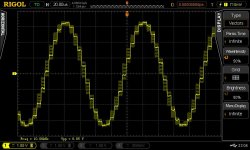
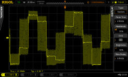
4-Deck DDDAC - some measurement
Hi all,
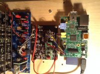
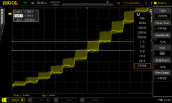
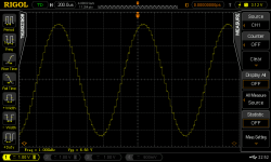
As I recently finished the build of a 4-Deck DDDAC, I did some function checks with my Rigol DSO. As there seem to be not too many images of measurements out there I thought I'd post some of the screens in this forum. My build is a combination of a 4-Deck DDDAC, an DIYINKH isolator, the DDDAC power supply, a RPi and a DIYINKH power supply for the RPi.
The measurements include the following:
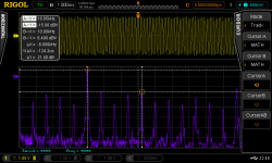
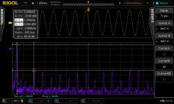
Moreover, what I don't understand further is that the FFT measurements did not change a lot when switching from a 44.1kHz to 19kHz sample rate. That's true even for the 10kHz signal, whereas the stair-steps make a huge difference in the time-domain but seemingly not in the frequency domain.
Maybe the FFT of my DSO is not good enough? Or am I missing something here?
Next I'm going to implement the Acko Reclocker - I wonder if this will lead to different measurement results or if they will be that small that they can't be seen with my equipment.
Best Regards,
Hermann
Hi all,
As I recently finished the build of a 4-Deck DDDAC, I did some function checks with my Rigol DSO. As there seem to be not too many images of measurements out there I thought I'd post some of the screens in this forum. My build is a combination of a 4-Deck DDDAC, an DIYINKH isolator, the DDDAC power supply, a RPi and a DIYINKH power supply for the RPi.
The measurements include the following:
- 1kHz + 10kHz test signals
- Broader and closeup views
- A FFT
Moreover, what I don't understand further is that the FFT measurements did not change a lot when switching from a 44.1kHz to 19kHz sample rate. That's true even for the 10kHz signal, whereas the stair-steps make a huge difference in the time-domain but seemingly not in the frequency domain.
Maybe the FFT of my DSO is not good enough? Or am I missing something here?
Next I'm going to implement the Acko Reclocker - I wonder if this will lead to different measurement results or if they will be that small that they can't be seen with my equipment.
Best Regards,
Hermann
An externally hosted image should be here but it was not working when we last tested it.
Attachments
-
 DDDAC-FFT-10kHz-44.1.png28.1 KB · Views: 109
 -
 DDDAC-FFT-1kHz-44.1.png27.1 KB · Views: 114
 -
 DDDAC-10kHz-192-closeup.png23.7 KB · Views: 96
 -
 DDDAC-10kHz-192.jpg66.4 KB · Views: 95
 -
 DDDAC-10kHz-44.1-closeup.png38.2 KB · Views: 102
 -
 DDDAC-10kHz-44.1.png25.9 KB · Views: 132
 -
 DDDAC-1kHz-192-closeup.png27.6 KB · Views: 137
 -
 DDDAC-1kHz-44.1-closeup.png26.9 KB · Views: 143
 -
 DDDAC-1kHz-44.1.png29.5 KB · Views: 140
 -
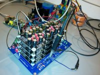 DDDAC-4Deck2.jpg416.4 KB · Views: 182
Hi all,
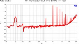
As I recently finished the build of a 4-Deck DDDAC, I did some function checks with my Rigol DSO. As there seem to be not too many images of measurements out there I thought I'd post some of the screens in this forum. My build is a combination of a 4-Deck DDDAC, an DIYINKH isolator, the DDDAC power supply, a RPi and a DIYINKH power supply for the RPi.
The measurements include the following:
To my mind the measurements look quite promising. What I don't really understand in detail, however, is the FFT: I personally expected to see lower harmonic distortion. The difference between the 1kHz signal and e.g. the 5th harmonic (6kHz) measured only -40dB and for 10kHz it's just -20dB.
- 1kHz + 10kHz test signals
- Broader and closeup views
- A FFT
Moreover, what I don't understand further is that the FFT measurements did not change a lot when switching from a 44.1kHz to 19kHz sample rate. That's true even for the 10kHz signal, whereas the stair-steps make a huge difference in the time-domain but seemingly not in the frequency domain.
Maybe the FFT of my DSO is not good enough? Or am I missing something here?
Next I'm going to implement the Acko Reclocker - I wonder if this will lead to different measurement results or if they will be that small that they can't be seen with my equipment.
Best Regards,
Hermann
Did you check my website for comparison?
An externally hosted image should be here but it was not working when we last tested it.
When looking at your measurement setup I see you put the earth of the scope to the positive output pin. Did you try making single ende measurements to avoid putting one output to your mains earth?
Otherwise hard to judge as I do not know what source you used, bit level of the sine waves etc.
I normally measure aproximately-55 to -60 dB
Hello,
I am thinking about having a custom toroidal transformer made for the power supplys.
How big should it be? How much current should the transformer be able to deliver for 15V and 9V?
Thanks.
chancenvergeber
Deep down we have some posts about this. In summary it came out that bigger is better, so not the technically minimum solution, but taking a nice fat 50 to 200 VA version. So may be you could limit your choice by available space or budget?
...
How big should it be? How much current should the transformer be able to deliver for 15V and 9V?
...
With a 4 dac boards the 12 volt supply draws 17watt and the Waveio about 5watt.
I'm using a 120VA transformer for the main 12volt supply which is plenty of headroom, imo and sounds great. Some suggested using up to 500VA but I've not seen anybody actually doing it.
Thanks.
From reading the posts about big transformers before, I got the impression that there is no real hard number. With my questions I just wanted to confirm that it is still like that.
I have no real space limitations and I think that a toroidal transformer with approx. 250VA and some extras for Hifi-use will cost around 70 Euro.
Thanks.
From reading the posts about big transformers before, I got the impression that there is no real hard number. With my questions I just wanted to confirm that it is still like that.
I have no real space limitations and I think that a toroidal transformer with approx. 250VA and some extras for Hifi-use will cost around 70 Euro.
You might also consider an R-core type transformer. Imho toriodals are the least good sounding. I have had better sonical results with a simple and cheap EI core, but best results are with R cores.
I think it might have something to do with the better isolation from mains.
Regards,
Separate bobbins for the primary and secondaries, hence the bandwidth that the transformer will couple is therefore limited, so then any noise on the mains is not coupled to the secondary. That's my limited understanding.
On top of the trans, is the choke filtering rather than cap filtering directly after the bridge rectifier. Many many options......
Cheers
Drew.
On top of the trans, is the choke filtering rather than cap filtering directly after the bridge rectifier. Many many options......
Cheers
Drew.
With a 4 dac boards the 12 volt supply draws 17watt and the Waveio about 5watt.
I'm using a 120VA transformer for the main 12volt supply which is plenty of headroom, imo and sounds great. Some suggested using up to 500VA but I've not seen anybody actually doing it.
I have a hand wound 300va for the DAC and 200 for the WAVIO small but noticeable improvement
Hi guys
It's been 3 weeks since my DDDAC was build and I have been playing a lot theese last days. I have to say that this dac is very good. As someone maybe remember I promised a shootout against my tweaked Buffalo IIIse dual mono.
1. "Digitalis" : dddac is more analog sounding, Buffalo have a small "edge" in direct comparason. This is very important for me as I play music for several ours daily.
The dddac is fantastic here. The music flow with ease and naturalnes in a way I never heard
before from a digital product, bravo.
2. Voices: Dddac is so natural, and again, no digital edge here. Buffalo have a very clear midrange, but the sound from dddac feels more realistic. Easier to believe what you hear.
3. Bass: After replacing the stock trannies with 250va on 12v, and 200va on 5v, ddac have the same authoroty at the lower end. Definition is very close race here.
4. Resolution: dddac seems to dig even deeper into the recording than Buffalo.
5. Musicality: dddac grab my attention from the first tone and don't let go. Buffalo does the same, BUT after a while my thoughts starts to think about other things than music.
Konklusion: well, no conclusion for now, and I will explain why.
Exa u2i vs, WaveIo : Buffalo use Exa, and as you know, dddac use WaveIo.
I had very hard to believe that dddac should be so much better than Buffalo. So i installed Exa in dddac and did an direct comparason against WaveIo.
Wow, I must say I am very surprised,,, whit Exa in use, dddac sounds almost as Buffalo. The digital edge and several things that was related to Buffalo's sound came back in dddac.
Switcing over to WaveIo, and everything was good again.
WaveIo is superb sounding compared to Exa. ( in my setup ) but I have seen other also have the same experience.
So there is one more thing to do, and that is to put WaveIo in Buffalo. As I'm not shure how to connect it properly to Buffalo, maybe someone here can tell me. I guess it's best to use the isolated i2s outputs ?
Thx
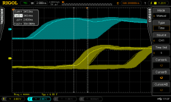
Some surprising measurements regarding Acko reclocker compared to isolator
Hi,
I yesterday finished the Acko S03 reclocker, so my chain is "RPi -> Acko S03 Reclocker with Crystal of 100Mhz -> 4 Deck DDDAC". What I was interested in was if and how the jitter would improve, so I checked the I2S signals with my DSO and would like to share my findings / thoughts:
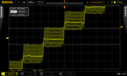
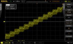
- Looking at the BCK signal first, one can see in the picture below that its edges are alternating to some degree (yellow signal is after the reclocker, blue is before, trigger is set to yellow signal).
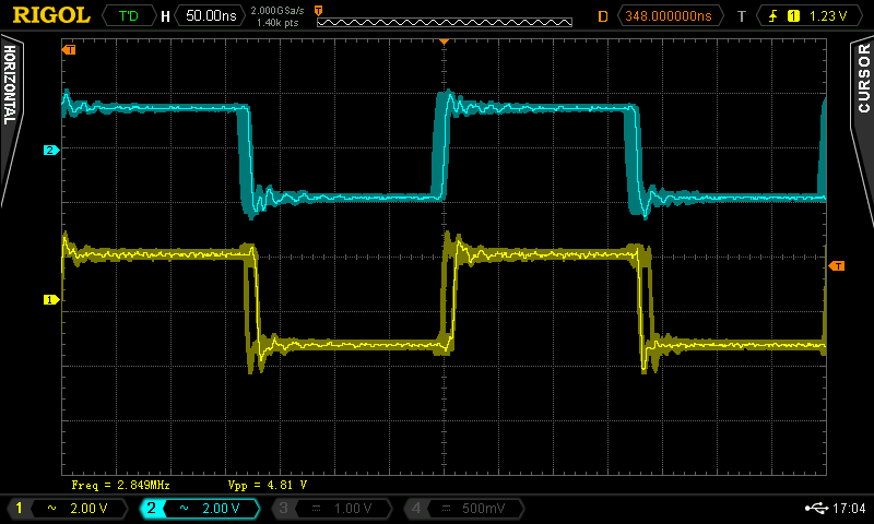
- A closeup shows that the jitter is quite exactly 10ns, which means that the signal shifts via the FF for one cycle of the 100Mhz signal from time to time.
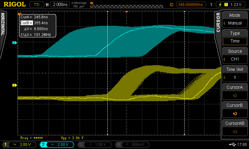
- Interestingly, another cursor measurement shows that besides to the 10ns alternating rising edge, the output signal has a jitter of approx. 2.6ns.

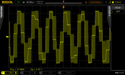
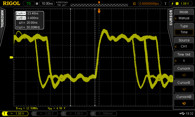
- The 192khz signal looks very jittered as well as can be seen here:
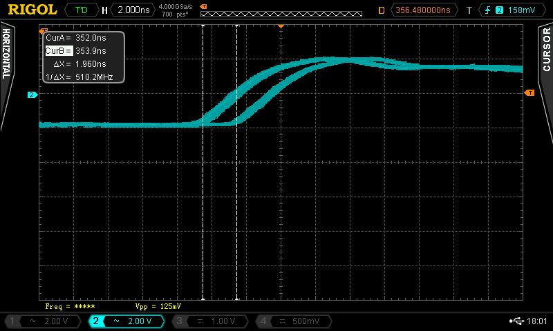
Next I checked the I2S signal right at the Raspberry Pi and found that the edges also alternate to some degree, however, the jitter is only at approx. 2ns - maybe this is due to the clock generation of the I2S signal via the 500Mhz clock?
What I wonder is the following:
- Am I doing something wrong? Maybe the implementation of the Acko reclocker is somehow flawed? Or I have an error in my measurement setup?
- Or: Is this the intended behaviour of the Acko reclocker? But - if yes, would the reclocker not add jitter instead of remove it?
Best Regards,
Hermann
Hi,
I yesterday finished the Acko S03 reclocker, so my chain is "RPi -> Acko S03 Reclocker with Crystal of 100Mhz -> 4 Deck DDDAC". What I was interested in was if and how the jitter would improve, so I checked the I2S signals with my DSO and would like to share my findings / thoughts:
- Looking at the BCK signal first, one can see in the picture below that its edges are alternating to some degree (yellow signal is after the reclocker, blue is before, trigger is set to yellow signal).
- A closeup shows that the jitter is quite exactly 10ns, which means that the signal shifts via the FF for one cycle of the 100Mhz signal from time to time.
- Interestingly, another cursor measurement shows that besides to the 10ns alternating rising edge, the output signal has a jitter of approx. 2.6ns.
- The 192khz signal looks very jittered as well as can be seen here:
Next I checked the I2S signal right at the Raspberry Pi and found that the edges also alternate to some degree, however, the jitter is only at approx. 2ns - maybe this is due to the clock generation of the I2S signal via the 500Mhz clock?
What I wonder is the following:
- Am I doing something wrong? Maybe the implementation of the Acko reclocker is somehow flawed? Or I have an error in my measurement setup?
- Or: Is this the intended behaviour of the Acko reclocker? But - if yes, would the reclocker not add jitter instead of remove it?
Best Regards,
Hermann
Attachments


- Home
- Source & Line
- Digital Line Level
- A NOS 192/24 DAC with the PCM1794 (and WaveIO USB input)