Hi OS,I added the EF/TMC to the TIS core. I am literally "blown away".
I have simulated and passed on most of DIY audio's designs.
THIS ONE is truly exceptional !
PS - I'll show "halcro" performance later.
Edmond , you are the "man". ("thinking outside the box")
OS
Isn't that too much praise? I'm just, like many others, "ordinary skilled in the art" of electronics. Perhaps more importantly, I'm not indoctrinated by that "blameless" concept.
")
Cheers, E.
Hi Bob,
I agree with most of your remarks, except the last one: "only a factor of about 2". This figure depends on circuit details. I have already said here that the Super-TIS output is very sensitive to a nonlinear (capacitive) loading. As a result, the distortion of this front-end together with your HEC outpput stage is quite high: THD20k = 20ppm. With a diamond pre-driver, see fig. 17 on this page, the distortion drops to 4ppm, i.e. 5 times lower (instead of ca.2). So it is well worth to cost of a few extra (small) transistors.
Cheers, E.
Good point - agreed.
Cheers,
Bob
@Keantoken,The Baxandall cascode can be better than the Hawksford because it doesn't send the cascode base currents through the VAS. But yes, depending on how you use them. there isn't always a big difference.
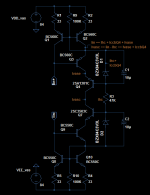
I've now mocked up the output of my VAS which shows how the Wilson mirrors and Hawksford cascode are tied together. I think these two wired up together like this form a very strong combo.
In this picture, I tried to replace Q4 and Q7 each by a Baxandall super-pair. And in this configuration, these didn't offer any improvement THD wise.
I've also tried to include current flows, though I've omitted factoring in base currents. I hope you can make sense of it. And perhaps you could tell whether a BSP should be advantageous here or that it indeed doesn't matter? All currents are summed back together when they go back into the mirrors. The cascode reference is actually a split-rail, taking a fixed current from the mirror outputs.
If I did something wrong, or drew wrong conclusions, just tell.. I can handle that
Attachments
Hi OS,
Isn't that too much praise? I'm just, like many others, "ordinary skilled in the art" of electronics. Perhaps more importantly, I'm not indoctrinated by that "blameless" concept.
Cheers, E.
Well said.
S
Well.... "Blameless" is a design-concept. Not a topology description per-se. We all apply "blameless" design phylosophies, which is the strive for linearization and removal/reduction of distortion components.
No, you are wrong.
S
Care to tell why exactly and link/show references as to why?No, you are wrong.
S
Using a super-VAS only make sense if the VAS was already the main source of distortion. If not, then changing the VAS will hardly change anything. It could be that the VAS load is the main source of distortion, not the VAS itself, so it's contribution is swamped. When I have a question like this I have to go through several steps of verifying where exactly the distortion comes from, so treat my response as my best guess, I guess.
As far as "Blameless", really it's best to be using the same dictionary as everyone else if you want to make sense to anyone but yourself. If you don't, or you invent your own definitions then you just make it impossible for people to know what you really mean. That doesn't mean you can't keep in mind the "real" definition, it's just an act of courtesy so that the interaction works out better for everyone.
People who read the books written about your work will use the terminology contained in them, so writing a really good book is the best way to pin down an effective terminology. But it's in the future, and communication takes place now. Polite and courteous people can always work out the communication bugs, it's really not a big deal.
I tested the VAS with an ideal OPS (infinite input Z) to exclude any loading contributions. Would you agree though that the ccb of Q4 and Q7 are recirculated as it would be with a non-mirrored VAS using a superpair?Using a super-VAS only make sense if the VAS was already the main source of distortion. If not, then changing the VAS will hardly change anything. It could be that the VAS load is the main source of distortion, not the VAS itself, so it's contribution is swamped. When I have a question like this I have to go through several steps of verifying where exactly the distortion comes from, so treat my response as my best guess, I guess.
I'm sorry, most of this is over my head; I simply repeated what people (of whom Bob C was one, in Doug's thread) explained to me what "Blameless" was about.As far as "Blameless", really it's best to be using the same dictionary as everyone else if you want to make sense to anyone but yourself. If you don't, or you invent your own definitions then you just make it impossible for people to know what you really mean. That doesn't mean you can't keep in mind the "real" definition, it's just an act of courtesy so that the interaction works out better for everyone.
People who read the books written about your work will use the terminology contained in them, so writing a really good book is the best way to pin down an effective terminology. But it's in the future, and communication takes place now. Polite and courteous people can always work out the communication bugs, it's really not a big deal.
When you run the VAS with a perfect output stage you eliminate a source of VAS distortion. The OPS input voltage is nonlinear, and this nonlinear signal leaks through the VAS. This is the source of distortion that the Baxandall cascode rejects better than the Hawksford. So it makes sense to me that the Hawksford would perform better because of the way you tested it, which isn't realistic.
I have to include a little detail though; there was a bit of loading, which were 2 very small value caps (~10pf) from VAS output to both the supply rails to stabilize it for testing. These probably swamped any possible differences. I have to figure out a better way to testWhen you run the VAS with a perfect output stage you eliminate a source of VAS distortion. The OPS input voltage is nonlinear, and this nonlinear signal leaks through the VAS. This is the source of distortion that the Baxandall cascode rejects better than the Hawksford. So it makes sense to me that the Hawksford would perform better because of the way you tested it, which isn't realistic.
P.S. in the complete schematic the VAS is loaded by Bob's HEC. The VAS input current runs at 21mA quiesent, which results in about 18mA for Ivasc in the picture, leaving 3mA for Ihc, the cascode ref rail.
P.P.S. I've dubbed the setup I've shown the "Wilson Enhanced Hawksford Cascode", or, WEHC. Oh the acronyms *grin*
Last edited:
When you run the VAS with a perfect output stage you eliminate a source of VAS distortion. The OPS input voltage is nonlinear, and this nonlinear signal leaks through the VAS. This is the source of distortion that the Baxandall cascode rejects better than the Hawksford. So it makes sense to me that the Hawksford would perform better because of the way you tested it, which isn't realistic.
I'm sorry, I have trouble understanding how this mechanism would work, could you perhaps illustrate how does 'this nonlinear signal' leaks through the TIS exactly?
Provided the LTP is properly linearized and the TIS isn't loaded with a too low impedance one would expect the TIS to generate the bulk of the distortion.
Using a super-VAS only make sense if the VAS was already the main source of distortion. If not, then changing the VAS will hardly change anything. It could be that the VAS load is the main source of distortion, not the VAS itself, so it's contribution is swamped. When I have a question like this I have to go through several steps of verifying where exactly the distortion comes from, so treat my response as my best guess, I guess.
As far as "Blameless", really it's best to be using the same dictionary as everyone else if you want to make sense to anyone but yourself. If you don't, or you invent your own definitions then you just make it impossible for people to know what you really mean. That doesn't mean you can't keep in mind the "real" definition, it's just an act of courtesy so that the interaction works out better for everyone.
People who read the books written about your work will use the terminology contained in them, so writing a really good book is the best way to pin down an effective terminology. But it's in the future, and communication takes place now. Polite and courteous people can always work out the communication bugs, it's really not a big deal.
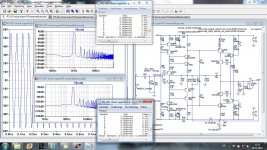
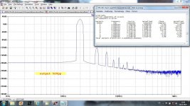
This IPS is a good example how low THD can be with ideal OPS. It uses "super-VAS" and have Loop Gain of 150dB at 10Hz and Open Lopp Gai close to 180dB. Is quite hard to tame the super-VAS, without cascade base stoppers and caps across the bias LEDs it oscillates. It is very sensitive to a output load, and to find good OPS for it almost impossible.
It shows almost no distortion at max output level. I simulated it with the standard EF triple and distortion goes up dramatically, and this is not OPS induced distortion only but the VAS distortion provoked with not ideal VAS load.
THD20k at 56Vpp at the output of the IPS is 0.000004% and goes up with the OPS to the 0.000341% and at max output to the 0.001983%, still good result but far from the super VAS potential.
Damir
Attachments
D3 & 4 force Q18 & 20 to work with exceptionally low Vce.
I see you have used bc5x0c here to help with this.
But would you get better CCS effect if the two diodes were replaced with low voltage red LEDs?
Would you have sufficient voltage available, if you lose another volt in the CCS?
I see you have used bc5x0c here to help with this.
But would you get better CCS effect if the two diodes were replaced with low voltage red LEDs?
Would you have sufficient voltage available, if you lose another volt in the CCS?
D3 & 4 force Q18 & 20 to work with exceptionally low Vce.
I see you have used bc5x0c here to help with this.
But would you get better CCS effect if the two diodes were replaced with low voltage red LEDs?
Would you have sufficient voltage available, if you lose another volt in the CCS?
This is about super-VAS suggested by keantoken. If you want to see more about CCS follow this link http://www.diyaudio.com/forums/solid-state/260308-gainwire-ngnfb-classb-poweramp-6.html#post4028879. I switched to that kind of CCS after Sergio showed it.
What has your response got to do with changing from one low voltage diode type to a higher voltage diode type?
I don't know that Thread, but the CCS is very similar to Roender's
It is not, a diode and BJT make CM, just read that thread.
D3 & 4 force Q18 & 20 to work with exceptionally low Vce.
I see you have used bc5x0c here to help with this.
But would you get better CCS effect if the two diodes were replaced with low voltage red LEDs?
Would you have sufficient voltage available, if you lose another volt in the CCS?
My post refers directly to your post1193It is not, a diode and BJT make CM, just read that thread.
I am asking whether replacing a diode (D3) with a red LED would improve performance.
the CCS is very similar to Roender's
It is a cascoded CCS. It is almost identical to Roender's cascoded CCS.It is not,
Last edited:
My post refers directly to your post1193
I am asking whether replacing a diode (D3) with a red LED would improve performance.It is a cascoded CCS. It is almost identical to Roender's cascoded CCS.
You don't want you accept my explanation and you don't want to read that tread I provided the link. It is Current mirror on the top and you can't change a diode for a LED, it is not current mirror any more. It is not cascaded CCS
Replace the diode with a BJT connected as diode and that could be more clear then.
Last edited:
D1 R4 Q18 is a CCS.
D3 Q17 adds a cascode to the CCS.
It is a cascoded CCS.
D3 defines the Vce across Q18.
Using a red LED, or two diodes, increases the Vce across Q18
This may make no difference to the performance of the CCS, or it may improve the performance of the CCS.
I don't know which.
I am suggesting you look into the change and after informing yourself you decide to leave as is, or change it to a red LED.
- Status
- This old topic is closed. If you want to reopen this topic, contact a moderator using the "Report Post" button.
- Home
- Amplifiers
- Solid State
- Has anyone seen this front-end before?