I just showed 4 different designs (the OP's stepped design, a simple tapped horn, a tapped bowtie and a front loaded horn), all almost exactly the same size with almost exactly the same response curve shape and sensitivity. Then I showed a different tapped horn compared to an OD tl (same tl, same driver location, but without the mouth side tap) and they were also the same sensitivity.
That's not convincing enough?
Thanks for putting in the effort, you are indeed very skilled in hornresp and with regards to system volume results I can not disagree.
I just want to clear up one very important thing regarding system volume and box volume, these are usually not the same, and I belive the question was :
Do you agree with Just a Guy's statement that a TH does not provide any additional efficiency gain compared to any other alignment for the same box volume?
Here is where i think we misunderstand each other, in practice, folding a tapped pipe (constant area) is relativly easy, no odd angles, less noncontributing internal volumes, which most likley makes it the most efficient alignment with regards to dB/m3 when built, TH and FLH on the other hand, although being very efficient, might result in a less efficient design with regards to dB/m3 once folded.
This is not to say it can't be, I'm jsut saying that reality some alignments are more efficient then others, considering cabinet external dimensions and output capacity for a given driver taking real world desired compression effects into account.
This is why i feel Circlomanens alignment proposal is so intresting, it could make for some very efficient cabinett designs with regards to dB/m3, maybe even rivaling that of TH's, even though it might be a bit ahead of it's time with regards to driver candidates, but considering the trends this might not be a problem for long.
You are correct, folding a tapered design requires a bit of extra space in the corners which adds a bit of box volume. Maybe 5 percent? BUT that extra space is not wasted, it adds to the total horn volume.
The OP's alignment proposal is a stepped horn, it's not anything new. It doesn't rival a tapped horn, it is a (stepped) tapped horn.
This has nothing to do with driver candidates. Choose any driver and any design and I can match it with the alignment of your choice. I think I proved that when I compared 4 different alignments with the OP's choice of driver and they all performed the same.
Using a stepped horn isn't a bad idea (I never said it was), it can help keep the compression ratio down in an undersized box. But you know what also will keep the compression ratio low AND allow you to use an even smaller box? A reverse tapered design (throat larger than mouth). THAT is the design to use if you want the lowest compression ratio and the smallest box for a given tuning using a standard flare shape. You can make it stepped too if you want.
Last edited:
Just a quick note to show how flare shape can be used. I built and measured this front loaded horn 3 or 4 years ago.
For this design the goals were:
1. Ruler flat response from 35 to 120 hz (a very unusual - and not necessarily desirable - goal for a massively undersized flh but I wanted to see how close I could get)
2. 100 liter size limit
It's got an odd flare shape, the last segment gets smaller towards the mouth and the mouth hole itself was quite small. The cumulative effect of those details lowered tuning and killed the rising response an undersized flh exhibits. The rest of the flare was carefully adjusted to get the ruler flat response.
I screwed something up probably during the fold or construction or maybe it's a measurement problem (my mic broke before I could measure in a more suitable environment) because the 90 hz dip wasn't supposed to be that big, but even so it's only a couple db deep. So I got fairly close to ruler flat response over the intended bandwidth.
The top line in the measurement is this horn. It was winter so the measurement was taken with mic just slightly inside the mouth to eliminate room effects. I don't think there's any smoothing. No eq or dsp applied.
This is a very unusual response for a 100 liter flh.
Adjusting flare shape is a very powerful tool. For the first couple of octaves above tuning you can make any response curve shape you want.
An externally hosted image should be here but it was not working when we last tested it.
An externally hosted image should be here but it was not working when we last tested it.
Guy,
Neat design - that is some seriously thin compression channel from the driver face. Is this one of those buyout 6.5in Aurasound drivers? That is a nice flat response and the way you have the expansion leading to a constriction reminds me of a ML-TQWTL but there is no direct radiator - it's all mass loaded front horn. I think you take a serious hit to SPL output with such a small constriction. I think for the same volume - a straight MLTL can also get a pretty flat response down to 35Hz. The output is not high though but you also have advantage of a direct radiator. Nice work on this box - very original.
Neat design - that is some seriously thin compression channel from the driver face. Is this one of those buyout 6.5in Aurasound drivers? That is a nice flat response and the way you have the expansion leading to a constriction reminds me of a ML-TQWTL but there is no direct radiator - it's all mass loaded front horn. I think you take a serious hit to SPL output with such a small constriction. I think for the same volume - a straight MLTL can also get a pretty flat response down to 35Hz. The output is not high though but you also have advantage of a direct radiator. Nice work on this box - very original.
The driver is Tang Band w6-1139si.
The small constriction (if you are talking about the mouth hole) is basically just a port and I made sure to make sure velocity was low, so low end output (near tuning) doesn't take much of a hit, but the sensitivity at the top of the passband takes a huge hit - no rising response.
There are some performance robbing features like the 5:1 compression ratio and the very large chamber but even so it seems to perform ok at high volume and these design compromises were necessary to achieve the number one goal:
Ruler flat response for the first couple octaves. From a 100 liter flh. Just wanted to see if I could. I was interested to see how far I could shift the natural response of a normal undersized flh by playing with it's geometry. It's a silly goal for practical purposes but it was an experiment.
The effective length of a horn is actually different than one measures with a tape measure because at the mouth of a normal symmetric horn, the pressure boundary is an arc where the center sticks out forward of the cabinet.
If I remember correctly, the old “rule of thumb” suggested the mouth bubble for a simple round horn is about 60% of the mouth radius, in other words, at the center of the horn, it protrudes that much forward of the wood. For a cd horn operating where it large enough to have directivity, that boundary is nearly perpendicular to the horn wall, following Keele’s pattern loss thumb rule.
Also, the “horn loading” effect has a “high pass” filter function based on the rate the area expands. For instance for a 30Hz exponential horn, the area cannot expand any faster than doubling about every 2 feet while for 300Hz, the area doubles about every 2.4 inches and so on.
The object of the BC horns is to have the rate of expansion proper so that the end of the bubble is formed by the 60 by 60 inch face dimension and have the inner part of the horn tie acoustically into that external bubble. The horn inside of the cabinet has a larger mouth than the opening in the side of the cabinet and but forcing the output to pass through a restriction puts it in the right place to tie into that bubble and in effect makes the mouth larger and horn path longer.
The restriction has a minor “low pass” effect and adds a little extra acoustic mass, neither of which are disadvantages. Internally, the BC speakers are regular front loaded horns, all of them are large enough where the Tapped design isn’t an advantage AND tapped horns “feel” the external loading less than FLH’s.
In the late spring of 2012 Anders Martinsson and i started to work on the THAM18 based on this idea. The magnet-structure and basket of the driver is protruding into the hornmouth and creating an constriction, massloading the horn slightly. We choose a very steep expansion for the last section to better "tie into" the front bubble of the horn. They are meant to be stacked 4 with the mouths in the middle to create a "baffle" 1200x1600 mm (47,2x63 inch) large which will create this support for a large bubble.
We got a lot of criticism for this, and few belived in our idea. Especially the last very steep section and the simulated lower corner (50Hz) in the spl-response was criticized. respons It is very confirming to read what Tom Danley wrote earlier in this thread about this effect.

Here is the Hornresp simulation comparing the THAM18 (266 liter) with a B&C18TBX100 with a TH18 (313 liter) from earlier in this thread with a 18SOUND 18LW2400 driver.
The THAM18 has measured response down to 38 Hz in 2 pi, and we read about someone claiming deep response into the low 20s cornerloaded in a living room.
Martinsson's Blog - THAM18 details
Cheers,
Johannes
I got the idea of the "front-bubble" and loading a baffle from a slot (horn-mouth) from this thread:
http://www.diyaudio.com/forums/multi-way/195734-nelson-pass-slot-loaded-open-baffle-project.html
http://www.diyaudio.com/forums/multi-way/195734-nelson-pass-slot-loaded-open-baffle-project.html
Circlomanen,
Do you know for a fact that the BC415 uses the B&C 15TBX100 drivers? If so, does anyone know what the volume of the cone front is? This may impact the sims if accounted for. For now I am going to assume it is like 3.5 liters. I used the basic dimensions from your post #32 and split that into 4 smaller (straight horns - no folds) horns which are then connected in a network like the drawing made by Weltersys in post #13:
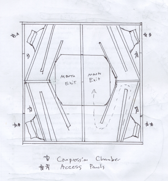
I have two horns with their mouths connected together and a side-firing short duct that mass loads the horn mouths. I am accounting for the large 60in x 60in baffle where the output duct is mounted in an offset for each side. Baffle effects and diffraction effects are included in the sim to the extent that the radiator location to the edge of the baffle is used for both the width and height. I am assuming the mouth (defined by the side firing mass loaded duct) for the combined two drivers (each side) is 24 in tall x 15 in wide.
I modified the HR dimension model to account for the drivers offset at a distance equal to 10in from the closed ends. In order to get the peak at 92Hz, and to get the bass knee at 38Hz like in the measurement on the BC415's spec sheet, the horn length had to be increased by 16in. Now thinking about how Tom Danley described the extra horn length virtually protruding out by 60% of the horn mouth diameter, this may make sense. The horn mouth width is about 30in at the widest point and 24in (estimated) in the smaller dimension. This is an average dia of 27in x 0.60=16.2in - which is seems like it is consistent with the concept of boundary-enhanced horn length extension. What I am not getting is the 114dB sensitivity at the peak of the bass knee. I am getting 110dB, which is why I am asking if Tom Danley actually uses the B&C 15TBX100 or some other driver with slightly higher sensitivity. My next sim will take it one step further and include the effects of all the folds and bends.
There is another variable one can play with and that is the compression ratio in the FLH front chamber. As drawn in the Fig above by Weltersys, the drivers will have to be rear-mounted onto the horn wall so that they can be accessed and serviced. This means that there is the option for having a throat at this wall to set a compression ratio, and whether or not Tom Danley uses any spacers to affect a change in the compression chamber volume is unclear. Nonetheless, it remains an additional parameter to play with. For now I am setting the throat area to equal to driver Sd and the throat length to equal 13 ply BB (0.709 in). I am also basing the rear chamber volume on the drawing which comes to 114 liters rather than 140 as in the HR input screen, the depth of the rear chamber is 9.5in according to the drawing.
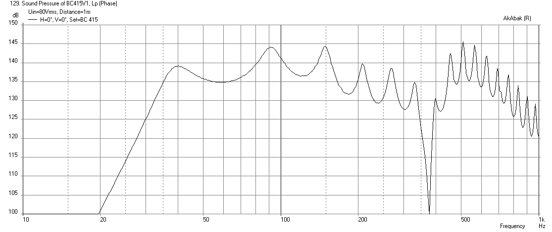
So here is what the Akabak sim gives as first cut at 1m and 2.83v wired 4 parallel:

Here is cone displacement at 80v to reach 11mm xmax (another question is if xmax is listed as 9mm why are you using 11mm?). I am using -24dB BW high pass filter at 35Hz as prescribed by spec sheet:

Here is the corresponding max SPL at 80v (this is with box sitting on ground in open - essentially 2pi but with mouth at 30in high above ground and mic at 30in above ground 1 m away). I am barely getting 140 dB so not sure what I am missing here:
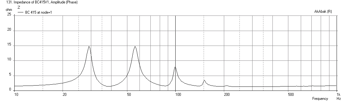
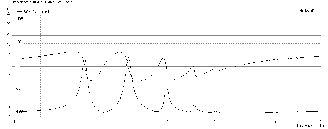
And here is the predicted impedance:
Do you know for a fact that the BC415 uses the B&C 15TBX100 drivers? If so, does anyone know what the volume of the cone front is? This may impact the sims if accounted for. For now I am going to assume it is like 3.5 liters. I used the basic dimensions from your post #32 and split that into 4 smaller (straight horns - no folds) horns which are then connected in a network like the drawing made by Weltersys in post #13:
I have two horns with their mouths connected together and a side-firing short duct that mass loads the horn mouths. I am accounting for the large 60in x 60in baffle where the output duct is mounted in an offset for each side. Baffle effects and diffraction effects are included in the sim to the extent that the radiator location to the edge of the baffle is used for both the width and height. I am assuming the mouth (defined by the side firing mass loaded duct) for the combined two drivers (each side) is 24 in tall x 15 in wide.
I modified the HR dimension model to account for the drivers offset at a distance equal to 10in from the closed ends. In order to get the peak at 92Hz, and to get the bass knee at 38Hz like in the measurement on the BC415's spec sheet, the horn length had to be increased by 16in. Now thinking about how Tom Danley described the extra horn length virtually protruding out by 60% of the horn mouth diameter, this may make sense. The horn mouth width is about 30in at the widest point and 24in (estimated) in the smaller dimension. This is an average dia of 27in x 0.60=16.2in - which is seems like it is consistent with the concept of boundary-enhanced horn length extension. What I am not getting is the 114dB sensitivity at the peak of the bass knee. I am getting 110dB, which is why I am asking if Tom Danley actually uses the B&C 15TBX100 or some other driver with slightly higher sensitivity. My next sim will take it one step further and include the effects of all the folds and bends.
There is another variable one can play with and that is the compression ratio in the FLH front chamber. As drawn in the Fig above by Weltersys, the drivers will have to be rear-mounted onto the horn wall so that they can be accessed and serviced. This means that there is the option for having a throat at this wall to set a compression ratio, and whether or not Tom Danley uses any spacers to affect a change in the compression chamber volume is unclear. Nonetheless, it remains an additional parameter to play with. For now I am setting the throat area to equal to driver Sd and the throat length to equal 13 ply BB (0.709 in). I am also basing the rear chamber volume on the drawing which comes to 114 liters rather than 140 as in the HR input screen, the depth of the rear chamber is 9.5in according to the drawing.
So here is what the Akabak sim gives as first cut at 1m and 2.83v wired 4 parallel:
Here is cone displacement at 80v to reach 11mm xmax (another question is if xmax is listed as 9mm why are you using 11mm?). I am using -24dB BW high pass filter at 35Hz as prescribed by spec sheet:
Here is the corresponding max SPL at 80v (this is with box sitting on ground in open - essentially 2pi but with mouth at 30in high above ground and mic at 30in above ground 1 m away). I am barely getting 140 dB so not sure what I am missing here:
And here is the predicted impedance:
Attachments


Last edited:
Do you know for a fact that the BC415 uses the B&C 15TBX100 drivers
No. I don´t know anything "for a fact" about the BC415...
I don´t think Tom Danley uses the B&C 15TBX100 anymore. It was (still is) a really good driver 5 years ago, but it is superseded by B&C 15SW115 in xmax, power capacity, motor structure, even Bl throughout the linear stroke of the voicecoil in the gap etc.....
Considering the 6800 watt continuous power rating, the 15SW115 is the only 15 inch driver that i know of capable of 1700 watt (6800/4).
another question is if xmax is listed as 9mm why are you using 11mm
9 mm is a theoretical number based on length of the voice coil etc... 11 mm is the measured xmax (xvar) at 10% distortion. I believe more in measurements then theoretical calculations... I wish everyone would settle on "xvar"...
Cheers,
Johannes
I like you simulations xrk971! Great job.
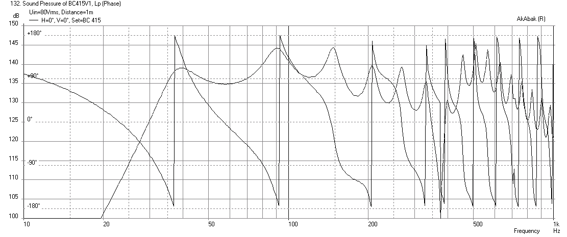
Do you have a phase simulation?
Cheers,
Johannes
Thanks!
So maybe I should sim with B&C 15SW115? I like the measured xmax too, never heard of it called xvar though. Good to know now.
I am not sure which phase is being shown in spec sheet. Acoustic phase in mic measurement or impedance phase?
Here is Acoustic Phase:
Impedance Phase:
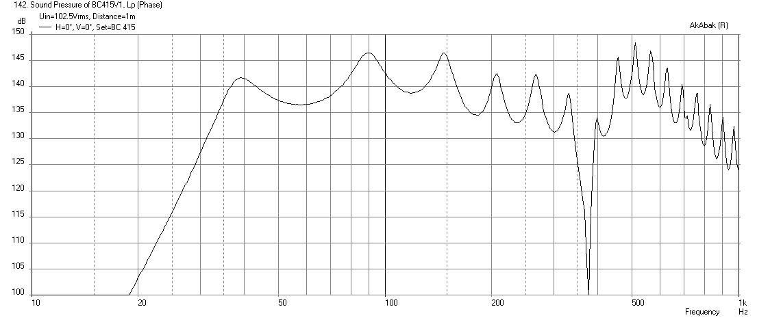
Here is the same speaker with the new 15SW115 driver - max SPL is now 142dB at 102.5 volts! to reach 13.5mm xmax:
Peak power into system is 6.43kW at 87Hz or 1608 watts a piece. That is some serious heat - you could cook hotdogs with the heat coming out the back vent on the magnet
")
Attachments


Last edited:
Peak power into system is 6.43kW at 87Hz or 1608 watts a piece. That is some serious heat - you could cook hotdogs with the heat coming out the back vent on the magnet
This is one of the reasons i thought it was some kind of tapped horn. The tapped horn usually have the magnet in (or near) the mouth where there is a lot of air moving by at high speed cooling the magnet and helping vent away heat from the voice-coil.
If it is rated for a continuous 6800 watts and 27000 watts peak, there must be some cooling of some kind. Even though the horn is really good at transforming electricity to sound, with comparably less losses (heat) along the way, there will still be lots and lots of heat to dissipate away. There is still an itch way back in my mind trying to tell me there is something else going on. Based on cooling issues alone, i would prefere to build some kind of tapped horn in these dimensions, rather then a normal FLH. The tapped horn is a FLH, but with a tap into the horn to fill a dip in the response... Something to ponder....
Cheers,
Johannes
1) The B&C 15SW115 is a good guess, DSL uses the driver AES power specs for their specs, for instance the TH-118 still has the higher power rating of the 18Sound 18" driver pictured on the spec sheet even though they have long since switched to the BC18SW115-4. The BC18SW115-4 has a higher 16mmXvar (where magnet strength is falling by 20% IIRC the Xvar definition) than it's Xmax of 14mm, it produces little distortion at Xvar.1)So maybe I should sim with B&C 15SW115? I like the measured xmax too, never heard of it called xvar though.
2)I am not sure which phase is being shown in spec sheet. Acoustic phase in mic measurement or impedance phase?
3)Here is the same speaker with the new 15SW115 driver - max SPL is now 142dB at 102.5 volts! to reach 13.5mm xmax:
4)Peak power into system is 6.43kW at 87Hz or 1608 watts a piece. That is some serious heat - you could cook hotdogs with the heat coming out the back vent on the magnet
2) Acoustic phase. Set your phase to the correct delay time in your sim and it will unwrap all those 360 degree turns in the LF and look similar to what the BC specs show.
3) Use the 13mm Xvar figure, in the case of the 15SW115 Xvar is slightly less than Xmax, the magnet would be running out of "push" at 13.5mm, especially with the BC loading.
4) With "typical" music (like this 58 year old man listens to) dynamic range is usually (a lot) more than 12 dB, the dynamic range of pink noise. When testing the 18SW115-4 with pink noise peaking at around 2500 watts, the vent output was just warm. Even using 77v sine wave, the output was never near hot dog cooking temperatures, though I never ran for more than 30 seconds or so, as that level well exceeds the average power contained in the 6 dB crest factor AES rating. The 15SW115 has the same power rating as the 18SW115, I'd expect it to be fine with "normal" music peaking well over 3400 watts, but for Skrillex and such EDM with LF dynamic range of 3 dB, set RMS limiters to around 850-1000 watts to keep the magic smoke from creeping out of the genie's chamber :^).
My back of the envelope drawing was based on the BDEAP (Tom's similar design for Sound Physics) prior to the later BC18 configurations pictures Ivan Beaver posted, which seem to confirm the similarity of the two designs.
Of further "bread crumb" info, DSL tests trying the 15SW115 in the TH115 rather than the 15TBX100 did not result in enough output difference to warrant changing to the far more expensive driver, the BC415 specs would indicate it is worth it in the BC application.
Got to get back to the shop and finish what I'm working on before any more "reverse engineering" ;^).
Art
Attachments


Last edited:
Darn. I was hoping someone would make a YouTube video of cooking a hot dog from the vent of a big pro sub woofer.
Weltersys, when you say adjust phase in the sim to unwrap the phase. Do you mean see what the delay is from the IR then apply an all pass filter delay to null out the delay seen in the IR? And that will flatten the phase?
Weltersys, when you say adjust phase in the sim to unwrap the phase. Do you mean see what the delay is from the IR then apply an all pass filter delay to null out the delay seen in the IR? And that will flatten the phase?
In order to get the peak at 92Hz, and to get the bass knee at 38Hz like in the measurement on the BC415's spec sheet, the horn length had to be increased by 16in. Now thinking about how Tom Danley described the extra horn length virtually protruding out by 60% of the horn mouth diameter, this may make sense.
All horns have the bubble.
Our simulators (Akabak and Hornresp) are aware of the bubble, they account for the bubble in all our simulations. Always have.
I don't think the boundary in this design is adding horn length, I don't think there's anything going on that Akabak can't handle when diffraction is introduced into the model. If boundaries caused more length, mounting a driver flush in a wall would add more horn length. It doesn't, although it may look similar to the effect of adding horn length. All it's doing is providing a boundary. The effect of that is diffraction. If we were to flush mount a horn mouth into a floor/wall junction of a very large wall (larger than the lowest frequency played through the horn), we would set our Ang to 1 pi (which effectively gives the diffraction profile of a very large floor/wall boundary) and trust the software to figure out the bubble math, and the sim would be accurate. For smaller boundaries like this a more flexible diffraction simulation is required, like what you are doing. I'm not sure why we suddenly don't trust our software to calculate the bubble.
I just checked out the spec sheet for the sub in question and your sim is remarkably close considering no one really knows the internal dimensions or driver used. There are a couple of tweaks you could make to the sim to make it look more like the spec sheet measurement before assuming the bubble is adding horn length in ways that it doesn't with all the other designs we see daily.
TD designed it so the frontal area and bubble area were equal. That doesn't mean we can't simulate the cab with our existing software or that the horn is operating in some strange new way. I'll be pretty surprised if someone can prove there's anything more than diffraction happening.
Last edited:
Our simulators (Akabak and Hornresp) are aware of the bubble, they account for the bubble in all our simulations.
Just to clarify - AkAbak uses the standard Webster plane wavefront model and does not take the "bubble" into account. The Hornresp isophase wavefront model does.
That is interesting, thanks.
I've never noticed much change in sims exported from Hornresp and imported into Akabak, so I thought they were doing pretty much the same thing.
Anyway, that doesn't indicate anything unique with this design, it would apply to every design with a hole in the box.
I've never noticed much change in sims exported from Hornresp and imported into Akabak, so I thought they were doing pretty much the same thing.
Anyway, that doesn't indicate anything unique with this design, it would apply to every design with a hole in the box.
Last edited:
I've never noticed much change in sims exported from Hornresp and imported into Akabak, so I thought they were doing pretty much the same thing.
The difference between the plane and isophase wavefront simulation models becomes more noticeable with Le Cléac'h, tractrix, radius and spherical wave horns, where the expansion profile is such that the wavefront at the mouth can be quite curved.
Attachments

- Status
- This old topic is closed. If you want to reopen this topic, contact a moderator using the "Report Post" button.
- Home
- Loudspeakers
- Subwoofers
- Danley BC-subs reverse engineered