Hello,
I hope this is the right forum to ask these question.
I recently got myself a used Adcom GFA 5400. It is the Version 1 made in Japan. As compared to my other Adcom 535L, it seems that the higher notes that a cello plays have kind of a nasally, harsh, scratchy, annoying sound. The highs sound a little bit more forward and harsh, vs the 535L sounds more smooth or laid back. These differences seem small to me, and I am not even sure they exist. So a couple of questions:
1) I read about the main difference btw bipolar and MOSFET amps is their distortion characteristics. What would be the most useful test for me to measure on the 5400 to see this (or rather, to differentiate its sound from the 535L)?
2) I would be willing to change out the caps or make a few other tweaks if I am pretty sure they would make a difference. So for example:
a) the power supply caps don't really look bulged, but the top are convex by about 1/16" of an inch. Worth changing out?
b) Any other caps worth changing out?
And what kind of measurement to make to confirm that these changes made a difference?
3) I would also like to cut down the gain by about 10 dB since I am driving it with a DAC directly. Where would be a good place to do it?
4) I read another thread where some guy kept increasing the bias to ridiculous levels, and claimed the sound kept getting better and better. Now the service manual says 35mV over .56 ohms, or 63mA. I briefly increased it to 180mA, but didn't really notice a big difference. I didn't want to toast the amp or anything. Is this worth doing?
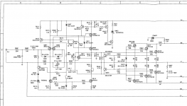
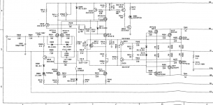
I don't know if I am allowed, but I can post a schematic if requested.
Thanks
I hope this is the right forum to ask these question.
I recently got myself a used Adcom GFA 5400. It is the Version 1 made in Japan. As compared to my other Adcom 535L, it seems that the higher notes that a cello plays have kind of a nasally, harsh, scratchy, annoying sound. The highs sound a little bit more forward and harsh, vs the 535L sounds more smooth or laid back. These differences seem small to me, and I am not even sure they exist. So a couple of questions:
1) I read about the main difference btw bipolar and MOSFET amps is their distortion characteristics. What would be the most useful test for me to measure on the 5400 to see this (or rather, to differentiate its sound from the 535L)?
2) I would be willing to change out the caps or make a few other tweaks if I am pretty sure they would make a difference. So for example:
a) the power supply caps don't really look bulged, but the top are convex by about 1/16" of an inch. Worth changing out?
b) Any other caps worth changing out?
And what kind of measurement to make to confirm that these changes made a difference?
3) I would also like to cut down the gain by about 10 dB since I am driving it with a DAC directly. Where would be a good place to do it?
4) I read another thread where some guy kept increasing the bias to ridiculous levels, and claimed the sound kept getting better and better. Now the service manual says 35mV over .56 ohms, or 63mA. I briefly increased it to 180mA, but didn't really notice a big difference. I didn't want to toast the amp or anything. Is this worth doing?
I don't know if I am allowed, but I can post a schematic if requested.
Thanks
I should read more articles about the Pass or MOSFET designs, but what is it about them that they need high bias to sound good? Or rather, that higher bias makes them sound better. If it's because it reduces the distortion, then why not design in lower distortion or higher feedback in the first place?
Yes, reading more of Pass will answer these questions. Even the classic Zen series of amp articles probably covers this subject well.I should read more articles about the Pass or MOSFET designs, but what is it about them that they need high bias to sound good? Or rather, that higher bias makes them sound better. If it's because it reduces the distortion, then why not design in lower distortion or higher feedback in the first place?
Basically, you can't just "design in" lower distortion. You do the best you can, with the devices that are available, at balancing all the necessary parameters to acheive the design goals. Most device parameters vary with variation of other parameters as can be seen in the curves on the datasheet. But, operating in a linear, low distortion manor is sometimes difficult. That might be graphed more as a strait line rather than a curve. You can see from some curves in the datasheet that as current goes up, the curve becomes more of a strait line.
Feedback is another touchy issue with some. Many think that although feedback lowers the measured THD numbers, the actuall residual distortion products of a high feedback circuit, although low, are more damaging to the sound than the simpler, lower order distorion of a circuit with much less or no feedback.
If you've been a member here for 10 years I would have thought you would have picked this up? You must of spent to much time in one of those other forum catagories. Passdiy and firstwatt www sites have many short papers and Zen articles that will get you up to speed on the Pass philosophy

Last edited:
Yep, that's most of it!Short version why 5400 doesn't live up to its potential:
3 pairs of output transistors and source resistors not matched well enough.
PS too small w too much ripple.
HS too small for glorious amounts of bias.
I'm sure there are plenty here that know better than me, and would probably even call bs- but I could hear when the bias was out on my gfa-535 ( high or low ) and it was always most evident in the treble. The original pots were finicky to set, and constantly drifting. Replaced them to alleviate the problem. Anything outside +-25% of the recommended bias setting always had me opening it for a reset. Having read so many threads here on the relationship between bias and sound quality had me wanting to set it higher, but my ears were telling me otherwise with those amps. Perhaps the 5400 is behaving similarly.
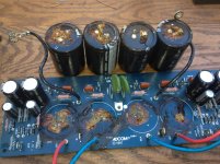
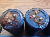
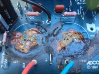
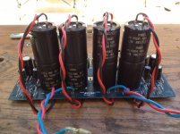
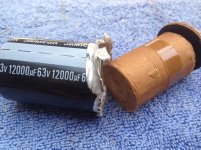
Not sure how much it adds to the thread but, I recently picked up a 5400 with some bad caps in the PSU. I was able to clean off the board good enough and Andersonix was nice enough to lend me some caps for a temp fix, I had to piggyback some smaller value caps but it works. Pictures below of the PSU board, bad caps and temp fix. I pulled one cap apart and it was near bone dry, only a few drops of electrolyte left inside the case.
I have 110VAC mains and re-tapped the transformer for 220VAC to lower the rail voltage. Now that I know I still have plenty of power at the lower voltage I should be able to recap with larger value caps on the stock PSU board.
I have 110VAC mains and re-tapped the transformer for 220VAC to lower the rail voltage. Now that I know I still have plenty of power at the lower voltage I should be able to recap with larger value caps on the stock PSU board.
Attachments
Is this even possible?
Currently on ebay there's a Stan Warren modded 5400: "which was custom modified by Stan Warren two years ago. He replaced some of the mosfet devises with super fast toshiba high current transisitors along with many other internal modifications. He felt that this was his best sounding modified Adcom. On the outside Vampire RCA’s, Furutech IEC and Gold binding posts were added. This amp sounds smooth yet detailed with allot of slam."
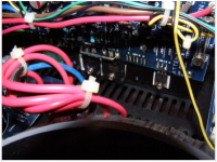
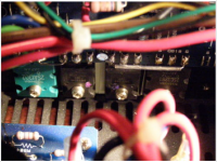
The pics appear to show one of the original IRFP240 Mosfets in parallel with a Toshiba 2SC3281 NPN (and similarly on the negative V rail, an original IRFP9240 Mosfet in parallel with a Toshiba 2SA1302 PNP) and one of the original Mosfets left out. It appears the Base of the 2SC3281 (in position Q618) is connected to the Source of the IRFP240 in position Q620) with an additional link (and similar connection on the -V rail).
What's going on there? Mosfets paralleled with BJT?
Adcom 5400 Amplifier Custom Modified 811900010002 | eBay
Currently on ebay there's a Stan Warren modded 5400: "which was custom modified by Stan Warren two years ago. He replaced some of the mosfet devises with super fast toshiba high current transisitors along with many other internal modifications. He felt that this was his best sounding modified Adcom. On the outside Vampire RCA’s, Furutech IEC and Gold binding posts were added. This amp sounds smooth yet detailed with allot of slam."
The pics appear to show one of the original IRFP240 Mosfets in parallel with a Toshiba 2SC3281 NPN (and similarly on the negative V rail, an original IRFP9240 Mosfet in parallel with a Toshiba 2SA1302 PNP) and one of the original Mosfets left out. It appears the Base of the 2SC3281 (in position Q618) is connected to the Source of the IRFP240 in position Q620) with an additional link (and similar connection on the -V rail).
What's going on there? Mosfets paralleled with BJT?
Adcom 5400 Amplifier Custom Modified 811900010002 | eBay
Attachments
HI Folks
One of the amps (Adcom GFA-5400) just landed on my doorstep and I'd like to play with it a bit.
To quote:
Short version why 5400 doesn't live up to its potential:
3 pairs of output transistors and source resistors not matched well enough.
PS too small w too much ripple.
HS too small for glorious amounts of bias.
Since I cant fix the heat sink problem, is it still worth improving the power supply
and match the transistors and source resisters and then maybe bumping the bias up a bit?
And..since I don't need all that power I was thinking of pulling one or two sets of transistors
which would effectively increase the heat sink area of the one set of remaining transistors.
Or should I just go build an F5?
Regards
Curt
First make sure the old PS caps are still good. Adcom acct dept made sure the newer the amp is, the worse quality the caps are.
You might even think about re-jumpering the primaries to run it on half voltage (30V), and then you can use 30V caps.
Play around with the 5400 to hear for yourself the effects of lower PS ripple and higher bias, and then use the 5400 half-voltage PS for your F5.
You might even think about re-jumpering the primaries to run it on half voltage (30V), and then you can use 30V caps.
Play around with the 5400 to hear for yourself the effects of lower PS ripple and higher bias, and then use the 5400 half-voltage PS for your F5.
Hello and thanks for the reply.
After reading your reply I am going to start back with the basics and check out those power supply caps
in both the gfa-5400 and also in the gfa-535 II I have.
For these amps, should I find a way to increase the supply capacitance while I'm in there?
I guess Im just worried about the inrush current of a larger supply capacitance and its effect on the power transformer at turn on.
Is it also worth replacing the standard diode bridge with fast diodes?
If yes, any favorites?
Thanks again
Curt
For what speaker load is this mainly intended?
If you're playing with the bias, you should also put in multi-turn pots and Keratherm Red insulators.
There's enough NTC for lots more caps, just not so much space. I use MSR series diodes, because of their soft recovery. Try the MSRF-1560, as it's fully insulated.
If you're playing with the bias, you should also put in multi-turn pots and Keratherm Red insulators.
There's enough NTC for lots more caps, just not so much space. I use MSR series diodes, because of their soft recovery. Try the MSRF-1560, as it's fully insulated.
Thanks for the great tips
NTC...Im having a hard time remembering what that stands for.
Its either an inrush limiter or some performance aspect of the power transformer.
As far as speaker load, thats a good question, made difficult to answer by virtue of the eclectic collection of speakers Im playing around with here.
Right now I am listening to a pair of pristine AR-1W woofers with Janszen 130's on top. A classic combo.
Over in the other corner of the living room is a pair of early Shahinian Obelisk speakers.
In the wings are a pair of Dynaco A-25's, a pair of Snell JII's and a pair of JIII's.
A set of Magenpan SMG-a's, various stand mounted 2 way monitor types.
As you can see...its all over the place
Curt
Right, there's an ntc thermistor in there already for some inrush protection.
Nice! I'm driving the ESL portion of a ML SL3 with an Adcom 5200 biased to 15W of class A (0.7A bias), which is a great match. Nelson used to be into ESLs too, but I don't know why he turned away. I guess they weren't loud enough back then?
I guess you need at least one low voltage, highly biased amp, and at least one high voltage, high current (double or triple outputs), less biased amp. So maybe keep the 5400 mostly as is (except for lots more PS caps for high current) and start an F5?
Right now I am listening to a pair of pristine AR-1W woofers with Janszen 130's on top. A classic combo.
Nice! I'm driving the ESL portion of a ML SL3 with an Adcom 5200 biased to 15W of class A (0.7A bias), which is a great match. Nelson used to be into ESLs too, but I don't know why he turned away. I guess they weren't loud enough back then?
I guess you need at least one low voltage, highly biased amp, and at least one high voltage, high current (double or triple outputs), less biased amp. So maybe keep the 5400 mostly as is (except for lots more PS caps for high current) and start an F5?
Hello again
OK, I have one last question before I commit to the mods suggested above.
Lets say 25 watts was plenty.
Lets say I do the mods suggested above to both a gfa-5200 and a gfa-5400.
So that's new/more caps, half voltage primary, bias turned up and matched transistors & source resisters for the 5400.
Would the 5200 be the better sounding amp due to the fact that it only has one set of transistors per channel?
I guess before I start on he 5400, I wonder if I should just find a 5200 given that at half power it still has enough power for me.
I must say, I like the way the 5400 grips the bass on the 4 ohm AR1W.
I wonder if I would lose that on the modded 5200?
Decisions decisions
Curt
You do not need both a 5200 and a 5400 to do this test. You have a 5200, 5300 and 5400 bottled up in your one amplifier case. I have been running a few tests on a 5400 that I recently purchased, here is a link to the thread. If you drop the rails to 30V (My 5400 was 29V at 20WPC Class A) by putting the transformer primaries in series then you can run as many output devices as you like. Try running it with a single set of outputs (2 devices) and compare with the original three sets and see if you like the results. I might suggest two complementary pairs per channel (4 devices). This will allow you to crank the bias per device up to a decent level and still have a good bit of low impedance drive capability. Mr. Pass has shown several times in the past that the higher you push the bias current per device the better the distortion gets. To a point anyway, IIRC he said after you get past 30W per device the reliability begins to go down.
Now the big hitter here will be how do you cool the small heatsinks. I kicked around the idea of installing a pair of very low speed 100mm fans. I found that it doesn't take much forced air flow to keep these sinks cool at 20 WPC RMS (40w PEAK) Class A. This is about 2.25A peak per channel so you'll need to dissipate around 65W per channel. I was estimating that a 15 - 20 CFM fan mounted directly to the backside of the stock heatsinks would allow you to run at this bias level or higher.
Does your amp have the small circuit board with the transformer in the front (opposite side from the power switch)? If so that board is a 12V power supply for the 555 timer circuits, if you get some low power 12V fans this board could run them.
As others have already stated you'll need to bump up the PS capacitance to maximize performance due to the higher current draw.
These 33k uF caps are a drop-in and not too expensive. If you want to pay a bit more you could buy these 47K uF CAPS which are also a drop-in. These are both 35 VDC rated, so once you install them there is no going back to the original 60V+ rails....
In the end even though I like a challenge I decided not to mess around with making the stock 5400 case work. I am going to transplant the channel boards into a much larger case so that I can get 60 - 70 WPC Class A out of it.
- Status
- This old topic is closed. If you want to reopen this topic, contact a moderator using the "Report Post" button.
- Home
- Amplifiers
- Pass Labs
- Some questions on an Adcom 5400