I think that after several flea powered SE amps build during last five years it'd be now time for a 20W, 845 based, one.
In order to avoid a 100 lbs. chassis I'd really like to keep PSU and amp separated. There'd be a cable about 2 or 3 feet long that'd come directly out the amp, but on PSU chassis I will need a connector.
High voltage cables are not a problem, but I'm a bit worried about connectors.
It looks like even military, or other quality connectors, indicates much lower DC voltages than required 1KV on their datasheet.
What should one do??? What can I safely use?
Output transformers and HV.
I will set B+ somewhere between 900 to 1000V, not over. I'm not interested, at all, in experimenting corona effect related phenomenoms....
My preferred output transformers winder guarantees its up to 800V only.
He says that he'd use different isolating materials to go higher... but sound would suffer so he simply doesn't produce them. These are EI, unpotted, trafos.
But looking around on the internet it seems to me that you can find similar build transformers with almost no HV limitations. Often they talk about testing at 2KV and nothing else.
Could someone expert of HV transformers give me suggestions on the matter?
Thanks!
If you design for 1000V, connectors should be rated at least twice that much. Here you get into very specialized components. These kind of voltages used in radars, power transmitters etc. I would recommend to ask HAM folks about what they use in their kW and higher RF amps.
Or you could do something simpler, make 2 monoblocks with the power supply included on each mono chassis.
That's how I usually build. All my little amps are mono chassis. Same idea was initially for these possible 845.
But this time I want to use stacked power supplies. This means 3 different DC voltages. There will be all film caps and inductors and tube rectifiers. The same in mono would be too bulky.
Furthermore some very experienced builders told me that completely separated PSUs might not be superior to a single one. Imaging could be better with one shared B+
Anyway this time space and weight is problem. Also 845s filaments will be current regulated (best methode for DHT, no doubts). So a couple more of other big power supplies, with their heatsinks.....
Several of the standard RF connectors are rated sufficiently high to handle the 1kv at the current levels you need. I am fairly certain that the usual PL-259/SO-239 combo is sufficient. RG-8 size coax is also rated high enough, and has the plus of a shield as well.
Millen made a HV connector, you can look that one up too.
One can build a HV connector using standard pin tip and pin jacks, what is done is that there is added insulation required on both the plug and jack side. Of course these are not positive locking unless modified appropriately.
HV wire is available without much trouble.
_-_-
Hi,
Sorry to say so but that's another "Urban Myth"
Cheers,")
Furthermore some very experienced builders told me that completely separated PSUs might not be superior to a single one. Imaging could be better with one shared B+
Sorry to say so but that's another "Urban Myth"
Cheers,
You need something like this GES Electronic & Service - High Voltage Connectors But they are likely not cheap.
Hi,
Sorry to say so but that's another "Urban Myth"
Cheers,
Might be... or might be not. It's audio baby! NOBODY has truth in his pockets.
Note I used "might" and "could" terms. Not incidentally
Not if the cable was permanently attached to the amp side, like you said.. Then the HV is only exposed in the female socket on the power supply.
But, my point was if you can't find a HV multi-wire connector, you could use a separate HV connection for the B+ wire alone, and the rest in one standard multi-wire connector.
But, my point was if you can't find a HV multi-wire connector, you could use a separate HV connection for the B+ wire alone, and the rest in one standard multi-wire connector.
Transmitter connectors
Good evening Fralipo,
yep...know that problem very well.
Then i switched to military style connectors as are made for the same purpose. But then in less friendly environment than your listening area.
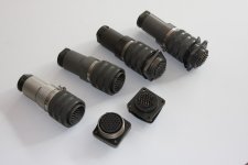
For my TB3/1000 amplifiers i used serious size Bendix connectors. They have seen 1400 V / 250 mA (B+) and 12V / 8A (filaments) besides all more sane voltages/ampères.
And they are running for about 10 your now (started as a 833A amplifier with 10V / 10A on the filaments) without any problem.
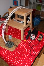
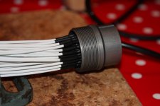
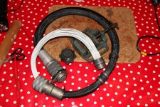
Just finished a new umbilical for an upcomming project (needed 30+ pins for 2 mm2 cables). See pics. Also from my big amp with external supplies using same style connectors.
But i'm afraid AVP1 is right: these connectors are not for free.......
How many wires do you need to connect ?
Reinout
Good evening Fralipo,
yep...know that problem very well.
Then i switched to military style connectors as are made for the same purpose. But then in less friendly environment than your listening area.
For my TB3/1000 amplifiers i used serious size Bendix connectors. They have seen 1400 V / 250 mA (B+) and 12V / 8A (filaments) besides all more sane voltages/ampères.
And they are running for about 10 your now (started as a 833A amplifier with 10V / 10A on the filaments) without any problem.
Just finished a new umbilical for an upcomming project (needed 30+ pins for 2 mm2 cables). See pics. Also from my big amp with external supplies using same style connectors.
But i'm afraid AVP1 is right: these connectors are not for free.......
How many wires do you need to connect ?
Reinout
Attachments

Perhaps a compromise: position a HV B+ supply on each mono amp, with all other powering from a common power module. The HV B+ mains supply could be interlocked with having correct power to the amp from the common power module. Then all your cabling and connectors revert to standard issue.
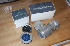
In my GM70 amp I use Amphenol MIL spec connectors to carry 1100v between the PSU and the amp.
Bought them from Mouser.
Links:
- plug $19
- receptacle $19
- bushing $10
edit: and I use a microcontroller for safety, interlocking and bias control
edit2: all of the soldered connections are varnished and covered with heat shrink tube
Bought them from Mouser.
Links:
- plug $19
- receptacle $19
- bushing $10
edit: and I use a microcontroller for safety, interlocking and bias control
edit2: all of the soldered connections are varnished and covered with heat shrink tube
Last edited:
Thank you for all the informations!
It's now clear which kind of connectors are required.
At this stage I'm only collecting informations for a future amp. I don't know yet how many wires I will need to connect. And, yes, building again two completely separated mono amps attracts me much, but they'd really be too bulky and heavy.
It's now clear which kind of connectors are required.
At this stage I'm only collecting informations for a future amp. I don't know yet how many wires I will need to connect. And, yes, building again two completely separated mono amps attracts me much, but they'd really be too bulky and heavy.
Rather than varnish, there is high voltage "Corona Dope" which is specifically designed for the purpose.
GC Electronics - 10-4702 - Chemicals - Coatings & Paints - Allied Electronics
GC Electronics - 10-4702 - Chemicals - Coatings & Paints - Allied Electronics
Usage of shielded cables and coaxial connectors in audio for HV in really unusual, but could be feasible. Apart that you'd have 1KV on a free, completely exposed pin..... it sounds like it'd be carefully avoided to me!
The umbilical for my Hallicrafters HT-45 "Loudenboomer" KW amplifier is a male fixture which runs FROM the amplifier TO the power supply. It's a phenolic fixture and doesn't appear to be expensive. I think one could design an interlock which would not allow the power supply to operate until it sensed that the cable was properly connected.
- Status
- This old topic is closed. If you want to reopen this topic, contact a moderator using the "Report Post" button.
- Home
- Amplifiers
- Tubes / Valves
- 1KV umbilical cords.... and other HV issues