Hello.
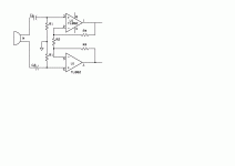
This is a circuit for a Samson C02 microphone that was brought by a generous contributor who I'd credit if I remembered who it was but this will have to do.
http://ap23-images.s3.amazonaws.com/samson-co2.jpeg
I would like to use it as a general purpose single-to-balanced converter. I can provide the phantom voltage. It would be handy, though, if it had gain, and I'm not smart enough to look at it and make any educated guess whether it does.
Is there anyone out there who could look at this and make such a guess? Or who knows whether microphone circuits like this characteristically have gain? And even maybe a guess as to how much, generally?
Thank you.
B
Thank you.
I wonder whether I could add a gain stage somewhere. Maybe decrease R4 so I can pull 9V for an input stage. I don't need super high impedance.
Depending of the technology you want to use (Bipolar, JFET, MOSFET, Tubes, opamps.), then you can add the gain in the stage following this, or in another preceding. This depends on if you want to get amplifier symmetrical or single ended. A simple stage that can do both in the same stage is the companion picture. R1 must be equal, and aproximate to the specified mic load (47Kohms??) and eventually you can put here a capacitor to tune the mic, in case of magnetic one. The stage gain is about (2R4/R2) +1 and R2 may be variable to adjust gain. Also, here, in // to R4 you can add tone compensation networks as desired, symmetrically placed on both R4's. Of course, you can use another opamp of your taste.
Use split power source (As example, 2 9V batteries), correctly decoupled, or single supply, tying the ground to a voltage divider at 1/2 VCC. This schematic has both, low output impedance, and as gain as you need for normal purposes.
Attachments
Last edited:
... whether microphone circuits like this characteristically have gain? And even maybe a guess as to how much, ...
Of course it has the gain - for 1V single-ended input you get close to 2V differential output, so the gain of the circuit (sch. in post #1) is about 6dB (there are some small loses due to internal resistance of active parts).
There are no NPNs in the sch linked in post1.
Hey, you are correct.
They are PNP's.
That makes the circuit more...mysterious.
")
DUG, The post #1 schematic is supposed to be the internal circuit of a Samson C02 mic and phantom powered in the normal way, 48V via 6K8 to each line. What's mysterious about it?
Possibly that I don't understand how phantom power mikes work.
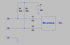
Rather than me trying to explain it in words, here's a very simplified form of the phantom power source in a Mic preamp. Put it up against the right hand side of the post #1 circuit to see how the DC current flows.
This is the standard 48V phantom power method used for balanced condenser mics the world over (there are other types)
The answer to your original Q is that the return path is through the Zener and the FET via its drain and scource R's
This is the standard 48V phantom power method used for balanced condenser mics the world over (there are other types)
The answer to your original Q is that the return path is through the Zener and the FET via its drain and scource R's
Attachments
I would not design the circuit with Ic controlled with a single resistor (R5 / R6)
But that is just me.
In its defence, it doesn't have to ouptut much signal - about 1V absolute max.
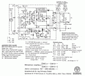
It's based on the circuit in the Schoeps CMC-5 mic body below.
The extra circuitry at the bottom is the 60V bias supply for the condenser mic capsule. The Samson CO2 doesn't need it as it's an electret mic.
Attachments
EssB, Is this an example of the circuit inside the mic preamp for the P48, or is this supposed to be within the mic circuit in order to receive P48 from the mic pre? I have seen this before, I am just confused by this context. Thanks!
Rather than me trying to explain it in words, here's a very simplified form of the phantom power source in a Mic preamp. Put it up against the right hand side of the post #1 circuit to see how the DC current flows.
This is the standard 48V phantom power method used for balanced condenser mics the world over (there are other types)
The answer to your original Q is that the return path is through the Zener and the FET via its drain and scource R's
That is the circuit inside the mic preamp, not the one inside the mic.
I would note that there is a subtle issue with P48 in that a cable going short can dump the charge on the preamp input coupling caps into the preamp input base/emitter junction which is not a healthy failure mode.
There are ways of dealing with it, but it does need consideration.
Regards, Dan.
I would note that there is a subtle issue with P48 in that a cable going short can dump the charge on the preamp input coupling caps into the preamp input base/emitter junction which is not a healthy failure mode.
There are ways of dealing with it, but it does need consideration.
Regards, Dan.
Just to be clear (as people often refer to the mic's internal amplifier as a mic pre), you mean that is the power circuit inside of the mic pre that provides P48 to the mic's internal amp through the XLR connection and not the circuit inside the mic's internal amplifier, correct?
- Status
- This old topic is closed. If you want to reopen this topic, contact a moderator using the "Report Post" button.
- Home
- Source & Line
- Analog Line Level
- Does this circuit have gain?