ohh oke, but I have also amps, I try not to overload me, because to much is not oke for a human.
I agree spekaer technologie has still an very long way as the only technology with the lowest efficiëntie
horns do help with it thanks to the old time where amps are very low power.
But some question about the cone volume calculator in your program
D1 D2 is this the outside of the speaker or the surround? I gess I have to measure half of the surround and not the outside speaker house itself, the rest speaks for itselfs.
thanks
kees
Last edited:
D1 D2 is this the outside of the speaker or the surround?
Hi Kees,
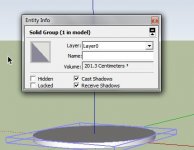
D1 is the inside diameter of the mounting sealing strip.
D2 is the inside diameter of the diaphragm suspension.
See the 'Driver Front Volume' section of the Hornresp Help file for further details.
Kind regards,
David
I did try it and get for phillips 8 inch 448.44 cm2 now I ask, this give trouble in VTC who is for best respons 413 cc .
I have to include the cone square cm2 to it, make it troublesome sim, where I have to include this in VTC or ATC? vtc is cubic cm, and atc square, there I have included the cone surface who make the sim oke.
design has two woofers do this mean I have to devide ports and such it is a synergy.
speaker has nice graph, but need to now where to include cone surface in this case 448.44 cm2.
thanks david.
kees
Attachments
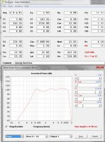
Keep in mind that a free standing synergy horn should be simulated in 4Pi.
2 Parallel speakers with 4.1 Ohm have a sum Re of 2.05 Ohm. You now have 2.83 Volt into the system. Double click on Eg and enter 1 Watt into 2.05 Ohm to get a more realistic SPL Data (it looks loud now, after adjusting you will have a much less louder system).
2 Parallel speakers with 4.1 Ohm have a sum Re of 2.05 Ohm. You now have 2.83 Volt into the system. Double click on Eg and enter 1 Watt into 2.05 Ohm to get a more realistic SPL Data (it looks loud now, after adjusting you will have a much less louder system).
Keep in mind that a free standing synergy horn should be simulated in 4Pi.
2 Parallel speakers with 4.1 Ohm have a sum Re of 2.05 Ohm. You now have 2.83 Volt into the system. Double click on Eg and enter 1 Watt into 2.05 Ohm to get a more realistic SPL Data (it looks loud now, after adjusting you will have a much less louder system).
Hi
This are for home use, she coming in a corner.
Ohh I did not seen this, I have now corrected it in serie connection 8 ohms, give 94 dB watt.
regards
kees
I have set it 0.5 pi, because of corner.
Get the horn some smaller, maybe with 6.5 inch it can even smaller.
stay on 2 way.
problem is VTC, it is cc, but front volume of woofer is 448 cm2 and this for
two woofers I do not now hronresp sim is per woofer, or dividing the ports and
such.
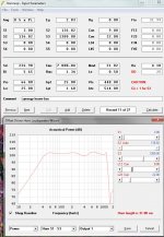
here is a sim who will not be right, because of vtc is 448 cc and not cm2 or i see
something wrong.
VRC is 66 cm2, here it is also be carefull that it fit dimensions, not so easy ehh the synergy.
Get the horn some smaller, maybe with 6.5 inch it can even smaller.
stay on 2 way.
problem is VTC, it is cc, but front volume of woofer is 448 cm2 and this for
two woofers I do not now hronresp sim is per woofer, or dividing the ports and
such.
here is a sim who will not be right, because of vtc is 448 cc and not cm2 or i see
something wrong.
VRC is 66 cm2, here it is also be carefull that it fit dimensions, not so easy ehh the synergy.
Attachments
here is a sim who will not be right, because of vtc is 448 cc and not cm2
Hi Kees,
Area in square centimetres is abbreviated to sq cm or cm2.
Volume in cubic centimetres is abbreviated to cc or cm3.
If the calculated driver front volume is greater than the required throat chamber volume, insert a filling plug in front of the driver diaphragm to reduce the volume to the desired value.
Kind regards,
David
Hi epa,
If all goes according to plan I hope to be able to release Version 35.00 containing the requested driver database functionality in the next week or so.
Kind regards,
David
I will let you know in due course.
If all goes according to plan I hope to be able to release Version 35.00 containing the requested driver database functionality in the next week or so.
Kind regards,
David
awesome.Hi epa,
If all goes according to plan I hope to be able to release Version 35.00 containing the requested driver database functionality in the next week or so.
Kind regards,
David

thank you so much for yet another nice feature.

Hi Kees,
Area in square centimetres is abbreviated to sq cm or cm2.
Volume in cubic centimetres is abbreviated to cc or cm3.
If the calculated driver front volume is greater than the required throat chamber volume, insert a filling plug in front of the driver diaphragm to reduce the volume to the desired value.
Kind regards,
David
Hi David
It is for a synergy, I can not make the port longer and so it is difficult/unpossible to fill that space, but some did use the vtc as a port dimension? and the atc as a chamber?
regards
kees
Hi David
Have I multiply the VTC and ATC when use more speakers? or do hornresp take this in account?
Atc I do not understand fully, when drawn in sketchup the cutput looks so big.
I presume that the circels in hornresp in chamber has to seen as devide in two so 50 procent smaller.
thanks.
kees
Have I multiply the VTC and ATC when use more speakers? or do hornresp take this in account?
Atc I do not understand fully, when drawn in sketchup the cutput looks so big.
I presume that the circels in hornresp in chamber has to seen as devide in two so 50 procent smaller.
thanks.
kees
Attachments
Last edited:
Hi Kees,
Hornresp does not automatically change the values of Vtc and Atc when multiple drivers are specified. The values used in the simulation are the same as those shown on the input parameters screen.
Atc is the cross-sectional area of the throat chamber, specified in square centimetres.
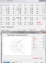
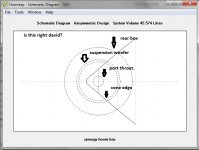
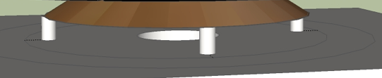
Your example is a little confusing in that the input parameters screen you show produces a different schematic diagram to the one provided.
The black dashed 'rear box' circle shows the circular cross-section of the cylindrical rear chamber.
The radius of the rear chamber is given by Sqrt((Vrc / Lrc) / Pi).
The black dashed 'suspension woofer' circle shows the circular cross-section of the cylindrical throat chamber.
The radius of the throat chamber is given by Sqrt(Atc / Pi).
The red dashed 'cone edge' circle shows the circular driver diaphragm.
The radius for two drivers connected in parallel is given by Sqrt(2 * Sd / Pi).
The black dashed 'port throat' circle shows the circular cross-section of the cylindrical throat chamber port.
The radius of the port is given by Sqrt(Ap1 / Pi).
Vrc is specified in litres and Vtc is specified in cubic centimetres.
Kind regards,
David
Have I multiply the VTC and ATC when use more speakers? or do hornresp take this in account?
Hornresp does not automatically change the values of Vtc and Atc when multiple drivers are specified. The values used in the simulation are the same as those shown on the input parameters screen.
Atc I do not understand fully, when drawn in sketchup the cutput looks so big.
Atc is the cross-sectional area of the throat chamber, specified in square centimetres.
I presume that the circels in hornresp in chamber has to seen as devide in two so 50 procent smaller.
Your example is a little confusing in that the input parameters screen you show produces a different schematic diagram to the one provided.
The black dashed 'rear box' circle shows the circular cross-section of the cylindrical rear chamber.
The radius of the rear chamber is given by Sqrt((Vrc / Lrc) / Pi).
The black dashed 'suspension woofer' circle shows the circular cross-section of the cylindrical throat chamber.
The radius of the throat chamber is given by Sqrt(Atc / Pi).
The red dashed 'cone edge' circle shows the circular driver diaphragm.
The radius for two drivers connected in parallel is given by Sqrt(2 * Sd / Pi).
The black dashed 'port throat' circle shows the circular cross-section of the cylindrical throat chamber port.
The radius of the port is given by Sqrt(Ap1 / Pi).
Vrc is specified in litres and Vtc is specified in cubic centimetres.
Kind regards,
David
Hi Kees,
Hornresp does not automatically change the values of Vtc and Atc when multiple drivers are specified. The values used in the simulation are the same as those shown on the input parameters screen.
Kind regards,
David
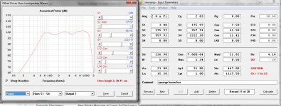
This mean I have to multiplay be two to get real sim? this will cause a unusable synergy horn, Maybe what some say, use akabak because hornresp is not for synergy,s others say it can be done and i agree because sims are very close, I have however sim par speaker not all at once.
Here I have some explaining, I did see after some search read ATC is Sd as start and VTC is room between speaker and horninput, But I have two horn inputs in the horn because it is senergy, you say that when to much between cone and horn I have to fill it up, this is true about high frequenty respons and this is what i need (1000Hz) like faseplug of something, but will not work in hornresp because it make port longer.
I think I have enough info about it, and understand what it does now.
regards
kees
Attachments
Last edited:
@kees
try doubling the width, not the length of your elements when using two speakers in your design. It should calculate the same as if you would double all the elements (if it were possible). Akabak is prefered for sinergy horns, becaus it is able to deal with multiple drivers for multi.way systemes (bss/mid/high in one sinergy horn) in one simulation and because it is able to add small lumbs (chambers/ducts..) and more complex horn-shapes than hornresp (which is restricted to the 4 segments). But if you put exact the same data in both, the sims are almost identical. You simply can not add more elements in hornresp - akabak can handle this.
try doubling the width, not the length of your elements when using two speakers in your design. It should calculate the same as if you would double all the elements (if it were possible). Akabak is prefered for sinergy horns, becaus it is able to deal with multiple drivers for multi.way systemes (bss/mid/high in one sinergy horn) in one simulation and because it is able to add small lumbs (chambers/ducts..) and more complex horn-shapes than hornresp (which is restricted to the 4 segments). But if you put exact the same data in both, the sims are almost identical. You simply can not add more elements in hornresp - akabak can handle this.
@kees
try doubling the width, not the length of your elements when using two speakers in your design. It should calculate the same as if you would double all the elements (if it were possible). Akabak is prefered for sinergy horns, becaus it is able to deal with multiple drivers for multi.way systemes (bss/mid/high in one sinergy horn) in one simulation and because it is able to add small lumbs (chambers/ducts..) and more complex horn-shapes than hornresp (which is restricted to the 4 segments). But if you put exact the same data in both, the sims are almost identical. You simply can not add more elements in hornresp - akabak can handle this.
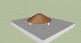
Thanks for your reaction, the VTC is just to big for the woofers for higher reach, only fill the chamber will work like I have drawn here.
You are right akabak is a lot better, I have some scripts who do help me, get them from others because I need a start somewhere, however when conic I can do with hornresp oke, when I do a closed chamber for the woofer I can try it out, but include a fill is in hornresp only possible when I now how much cc the fill is what I can use to make vtc smaller.
thanks for your tips, sometimes I think I have to do amps and not speakers, because the math is a lot more difficult, but I like it and so I go on.
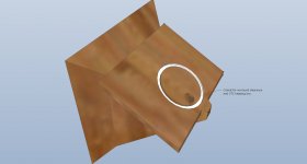
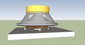
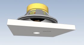
Picture is inverted cone, one mass, waves go around the sides of if down to the port, I do not now what happens, anly akabak can do this? but how.
What concerns hornresp can not do all driver at the same time, this is not a problem i do make just two sims .
regards kees
Attachments
Last edited:
Member
Joined 2003
Kees,Picture is inverted cone, one mass, waves go around the sides of if down to the port, I do not now what happens, anly akabak can do this?
The area between the dowels and the "phase plug" cone in your diagram also would extend the port length by the distance from the edge of the cone to the port exit, considerably lowering the band pass frequency. For this reason, and because an exit to the side of the cone, in the corner of the horn (assuming a 4 sided horn as you have portrayed) has less influence on the Synergy HF response, narrow "sausage shaped" side ports are generally employed.
Akabak or Hornresp model a circular port in the center of the driver, and assume a rigid, flat diaphragm with no breakup modes- at some point you are better off making prototypes and measuring response rather than endless modeling which won't represent all the physical realities.
Art
Attachments
Kees,
The area between the dowels and the "phase plug" cone in your diagram also would extend the port length by the distance from the edge of the cone to the port exit, considerably lowering the band pass frequency. For this reason, and because an exit to the side of the cone, in the corner of the horn (assuming a 4 sided horn as you have portrayed) has less influence on the Synergy HF response, narrow "sausage shaped" side ports are generally employed.
Akabak or Hornresp model a circular port in the center of the driver, and assume a rigid, flat diaphragm with no breakup modes- at some point you are better off making prototypes and measuring response rather than endless modeling which won't represent all the physical realities.
Art
This is what I was afreaid of, that it length the port and so destroy things.
It is thus that I was right, a flat cone is the best as little as air there
thanks
kees
If a flat "cone" could be made as light and rigid as a conical shaped cone (there is a reason they are called cones... a flat cone is the best as little as air there
") ) that would be nice for your purpose, but they can't, so we deal with the physical realities best as possible.
) that would be nice for your purpose, but they can't, so we deal with the physical realities best as possible.- Home
- Loudspeakers
- Subwoofers
- Hornresp