Mod pictures to activate the B&K 1607 Notch filter -
Here is my modification work for the active/passive 1607 notch filter. A 2pdt toggle (double contacts for reliable, good contact) switch to select active mode or passive, a 10 turn Spectrol pot with locking mechical turns indicator, circuit board for the opamp hung off the output socket.... plenty of room for batteries inside/below.
Thank you - ghg for the quick feedback/help which makes everything move along much faster for us all.
-Richard Marsh
Last edited:
active circuit -
Here is ghg's proof of concept circuit that I then used. I am tempted to use it more often now and the low opamp output Z is helpful in many applications.
The improvement in H2 loss is much better now (only 0.3dB) and helps reduce chance of errors; One less correction to think about or remember.
THX-RNMarsh
Last edited:
Details on Active 1607 modifications -
Last details on active mod ----> The batteries will be mounted on a removable rear panel for quick access for replacement.
The front shows the location of the passive-active switch, and added BNC active output, and new locking dial for the new ten-turn balance control.
Now it is fully self contained without taking up more work bench space.
Thx-RNMarsh


Done. Check !!
Last details on active mod ----> The batteries will be mounted on a removable rear panel for quick access for replacement.
The front shows the location of the passive-active switch, and added BNC active output, and new locking dial for the new ten-turn balance control.
Now it is fully self contained without taking up more work bench space.
Thx-RNMarsh
Done. Check !!
Last edited:


Hi all,
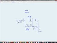
Inspired by GHG's 1607 modification here I'm considering changing a twin-t that I make for an HP339A oscillator variant (courtesy richiem's webpages) into a passive/active one.
I've calculated some values that should make it possible to switch between 20 Hz, 1200 Hz & 12 kHz (for 48 kHz multiplas) frequencies. I've drawn up a crude schematic for this (there's just a bit in Danish") ). The opamps are not LT1007 but OPA2134s.
). The opamps are not LT1007 but OPA2134s.
Might I have your input on whether or not this is correct - and if I should omit/change something:
- e.g. related to the input buffer?
- or remove the 500 ohm potmeter now that there are potmeters across the resistors?
Cheers,
Jesper
Inspired by GHG's 1607 modification here I'm considering changing a twin-t that I make for an HP339A oscillator variant (courtesy richiem's webpages) into a passive/active one.
I've calculated some values that should make it possible to switch between 20 Hz, 1200 Hz & 12 kHz (for 48 kHz multiplas) frequencies. I've drawn up a crude schematic for this (there's just a bit in Danish
). The opamps are not LT1007 but OPA2134s.Might I have your input on whether or not this is correct - and if I should omit/change something:
- e.g. related to the input buffer?
- or remove the 500 ohm potmeter now that there are potmeters across the resistors?
Cheers,
Jesper
Attachments
Hey Gary,
Thanks for your feedback ;-) I'll omit the 500 ohms then & try to see how it fares with the buffer.
Likewise
Jesper
Thanks for your feedback ;-) I'll omit the 500 ohms then & try to see how it fares with the buffer.
Have fun
Likewise
Jesper
Hi Dick & Richard,
Thanks for your suggestions but the LT1468 is one of the (few?) of the opamps you often mention that is not available from Mouser. And Mouser IMHO is very convenient to buy from as they take care of all the tax & customs issues which means that a component may cost the Mouser price + 25% tax whereas Digikey typically is (component cost + USD 25)*1.25. It doesn't matter if I were to buy for much money but in this case ... My intention was to start out with the OPA2134 (as I wrote in the post a bit back) as indicated on Dick's webpages for the other active Twin-T version.
Hope that works ...
Greetings,
Jesper
Thanks for your suggestions but
the LT1468 is one of the (few?) of the opamps you often mention that is not available from Mouser. And Mouser IMHO is very convenient to buy from as they take care of all the tax & customs issues which means that a component may cost the Mouser price + 25% tax whereas Digikey typically is (component cost + USD 25)*1.25. It doesn't matter if I were to buy for much money but in this case ... My intention was to start out with the OPA2134 (as I wrote in the post a bit back) as indicated on Dick's webpages for the other active Twin-T version.Hope that works ...
Greetings,
Jesper
Can you post the spice file? It would help.
The buffer will define the performance possible with the notch. The 100 Ohms on the output of the buffer probably is not necessary. I have a preliminary design for a buffer that borrows from some of the Shibasoku input amp but is mixed discrete/IC so its much easier to build. I'll find it and post it. One key issue is making the input impedance as high as possible. Otherwise it can affect the circuit you are testing. The same would be true for the amp at the output of the filter.
I posted an LTspice model in the Shibasoku thread of the bridged t filter they use. It may give some ideas on optimizations.
@1audio:
I'm also aware that I'm at a point where I have an inner urge to get this part of my projects completed and ready to use so that my main goal - to accompany listening with measurements on components and circuitry with a quite reasonable degree of precision -can be started.
However, I'm on the side following what you are finding out in the oscillator and shibasoku threads (subscribed).
But thanks for suggesting, Demian
Greetings,
Jesper
Hi ... I actually haven't made a spice simulation of this but calculated the values for the filter from richiem's (Dick Moore's) website. So LTSpice was mainly used to draw up the circuit in the "here and now".Can you post the spice file? It would help.
I'm also aware that I'm at a point where I have an inner urge to get this part of my projects completed and ready to use so that my main goal - to accompany listening with measurements on components and circuitry with a quite reasonable degree of precision -can be started.
However, I'm on the side following what you are finding out in the oscillator and shibasoku threads (subscribed).
But thanks for suggesting, Demian
Greetings,
Jesper
Hi all,
Inspired by GHG's 1607 modification here I'm considering changing a twin-t that I make for an HP339A oscillator variant (courtesy richiem's webpages) into a passive/active one.
I've calculated some values that should make it possible to switch between 20 Hz, 1200 Hz & 12 kHz (for 48 kHz multiplas) frequencies. I've drawn up a crude schematic for this (there's just a bit in Danish
Might I have your input on whether or not this is correct - and if I should omit/change something:
- e.g. related to the input buffer?
- or remove the 500 ohm potmeter now that there are potmeters across the resistors?
Cheers,
Jesper
Hi,
How did it go? Any progress to tell us about?
THx-RNMarsh
Hi,
How did it go? Any progress to tell us about?
THx-RNMarsh
Hi & thanks for asking ... As it is it's progressing slowly.
I had an issue with a high 2nd harmonic on my HP339 variant that I was unable to find out why was there. And then I somehow have happened to break "something" in the oscillator which further increased the distortion - I haven't yet had the time to find out what it is.
Currently I'm making (very) shielded cabinets for the A/D converter, the DUT, the twin-t filters, and the oscillator(s) so as to be able to measure very low levels of distortion/noise also at low frequencies. Battery supplies for all. It takes time, though ... so don't know when there's something to tell ...
Cheers,
Jesper
Another Thread
I started another thread. If y'all have any suggestions about
the B&K 1607 I'm cleaning up and trying to fix.
Here is a link to it.
http://www.diyaudio.com/forums/equipment-tools/259749-b-k-1607-repair.html#post4005099
I started another thread. If y'all have any suggestions about
the B&K 1607 I'm cleaning up and trying to fix.
Here is a link to it.
http://www.diyaudio.com/forums/equipment-tools/259749-b-k-1607-repair.html#post4005099
- Status
- This old topic is closed. If you want to reopen this topic, contact a moderator using the "Report Post" button.
- Home
- Design & Build
- Equipment & Tools
- B&K 1607 notch filter activated