Can anyone show me a VERY VERY BASIC idea /schematic ----on how to build
a simple bridge rectifier ---from a transformer 30 -0 30 ac out
--by very simple ---I mean no fancy IC ,S or complex circuits --
just a 20 DC from 30 V ac transformer --( 220 v AC in )
----do not want to include any lousy voltage regulator IC s that are not available
in the 3rd world --
just good ol diodes /capacitors please --
if impossible ---no problem !
will post a foto of the transformer ---was once used for a old TDA 140 watt guitar amp -- ( forgot the TDA #)
now I require 20 volt dc from it --
( printed on transformer as follows ) ---30 v --0 ----30 v---1.417 AMP
85 VA
nb ----no expert -- lotta hands on DIY experience---
prefer basic diagrams /sketches to complex un-fathomable-electronic jargon /theory
1.41 amps
Last edited:
I am afraid it is going to be difficult: peak rectification, whether half or full wave will yield more than 40V, average filtering with a choke (not included in your initial BOM) will give out 27V or so under load, and half-wave plus inductor filtering half of that.----do not want to include any lousy voltage regulator IC s that are not available
in the 3rd world --
just good ol diodes /capacitors please --
In any case, you' ll be seriously distant from your target voltage.
Completely avoiding active components would probably be possible in theory, using clever fractional voltage rectifiers, but honestly a cheap active circuit, not necessarily an IC will be much less costly and easier to source.
those voltage regulators I have seen on hundreds of bridge rect circuits ---are moon rocks here --take months to order from US supplies
all I want is some brave fella to post a simple schematic that ie possibly retro 60 /s
transistors --- mostly diodes
but its DIY ---I hate ic/s they are nightmares to handle /solder on home made circuits---
--hens teeth
there must be a circuit somewhere that's novice /idiot proof?
why is a " voltage regulator"
so necessary ---?--no -don,t answer that ---the quantum theory is way beyond
us laymen ----
I simply build a circuit --I do not delve into mathematical hieroglyphics --way too
complex --
all I want is a schematic with few parts --that works (not in theory ) but finger blistering practical application
the amp (TDA 2040---I built works ok 23 VOLTS ( 2 x 12 volt bulky heavy batteries) ---not nice
--that's why the TRANSFORMER /rectifier circuit is needed--
or is there a commercially available plug in 20 volt dc from ac adaptor unit --
available ? I doubt its cheap or small -probably cost a fortune /take 3 months to
import ---
ok thanks for the help ---
will keep looking
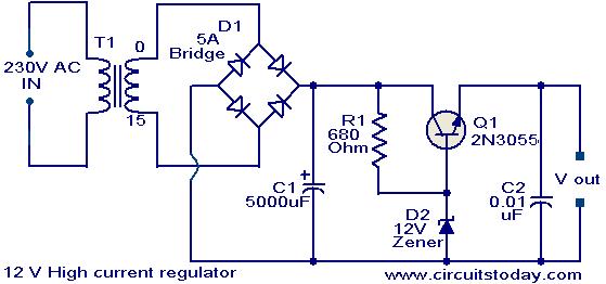
For 20 V out use a 21 V zener. R1=1k, Q1=Darlington. Use large heat sink for Q1.
An externally hosted image should be here but it was not working when we last tested it.
Last edited:
Can anyone show me a VERY VERY BASIC idea /schematic ----on how to build
a simple bridge rectifier ---from a transformer 30 -0 30 ac out
--by very simple ---I mean no fancy IC ,S or complex circuits --
just a 20 DC from 30 V ac transformer --( 220 v AC in )
----do not want to include any lousy voltage regulator IC s that are not available
in the 3rd world --
just good ol diodes /capacitors please --
if impossible ---no problem !
will post a foto of the transformer ---was once used for a old TDA 140 watt guitar amp -- ( forgot the TDA #)
now I require 20 volt dc from it --
( printed on transformer as follows ) ---30 v --0 ----30 v---1.417 AMP
85 VA
nb ----no expert -- lotta hands on DIY experience---
prefer basic diagrams /sketches to complex un-fathomable-electronic jargon /theory
1.41 amps
What you say is impossible, standard voltage regulators are easily available even in the 5th World, go figure.those voltage regulators I have seen on hundreds of bridge rect circuits ---are moon rocks here --take months to order from US supplies
WHERE do you actually live?
Unless you live *here*, of course:

A 3 leg TO220 voltage regulator?I hate ic/s they are nightmares to handle /solder on home made circuits---

TO 220 voltage regulator
thanku for enlightening me - only 3 legs! WONDERFUL!-assumed a the V REGULATOR was a
MILLIPEDE legged nightmare ( never seen one )
SO it resembles a power transistor ? that's great news !
still --it takes 2- - 3 month wait for snail mail to central Africa
but now I can at least solder with ease --16 legged IC ,s are hell with
my eyesight at 65 ---thanku ---so much!
WSJ ---
you are the man ! ---exactly what I asked for --really appreciate!
a few questions ----
1 ------21 volt ZENER diode ----yes---( from old tv set)
2 -------Q1 = darlington pair transistors-?--or the 2N3055 power transistor? ( got a few from salvage of scrap)
as you have shown a 12volt DC bridge circuit --do I copy exact circuit shown?
or the same circuit using those above components?
I have the above 220volt ---12 volt AC transformer---
can you put all modifications in place on another schematic ----?
sorry ---gross amateur ---a bit lost here---
will scrap the 30 ac transformer---
rebuild the above circuit---
thanku so much ---really learnt another quantum leap!
pc laptop supply
WOW --- thanku SRETEN--- so simple --I was blind! damn thing is in front of me !
Brighton to the rescue ! --brilliant !
had no idea my old PC supply was 19 volt ! ( should always read the fine print---) even then I assumed it was milliamps -----
2 . I amp ---astounding---
now I can scrap nasty bulky 24 volt lead weights( 4kilos)
for a small compact /lightweight solution --
so very grateful --
but I do intend building that rectifier circuit WSJ has so kindly
posted for me ----you guys are superstars for ideas --
( my innate curiosity has forced me to learn the hard way --))
after all --- this forum is called DIY --- SO --
despite Mr Faheys sarcasm -----(--Tom Hank,s Pacific island is a lot closer to USA than I am )--he has no idea what corrupt incompetent
3rd world customs / mail system can do to one,s parcels/composure!
will figure out how the rectifier circuit works --in practise
much more challenge involved in hands on ---instead of
easy to plug in sealed mysteries---
thanku all ---regards
throw that transformer in the bin....................... how to build
a simple bridge rectifier ---from a transformer 30 -0 30 ac out
--by very simple ---I mean no fancy IC ,S or complex circuits --
just a 20 DC from 30 V ac transformer --( 220 v AC in ) ..................
Buy the CORRECT transformer.
For 20Vdc use a transformer with one winding rated at 15Vac.
throw that transformer in the bin.
we who are from the third world do not throw anything away,
we make it work for our use....
Carl Winter, it is not enough to say you need 20volts dc, you have to tell us
20 volts dc at ?? current....
WSJ ---
you are the man ! ---exactly what I asked for --really appreciate!
a few questions ----
1 ------21 volt ZENER diode ----yes---( from old tv set)
2 -------Q1 = darlington pair transistors-?--or the 2N3055 power transistor? ( got a few from salvage of scrap)
as you have shown a 12volt DC bridge circuit --do I copy exact circuit shown?
or the same circuit using those above components?
I have the above 220volt ---12 volt AC transformer---
can you put all modifications in place on another schematic ----?
sorry ---gross amateur ---a bit lost here---
will scrap the 30 ac transformer---
rebuild the above circuit---
thanku so much ---really learnt another quantum leap!
Yes, use the same circuit with the component values I listed in the text. 30 VAC will be 42 VDC at the filter cap (30 VAC x 1.414 = 42 VDC). If you include the 1.2 volt drop from the bridge (42-1.2 = 40.8). 24 VAC would be a better voltage, but 30 VAC will work. If you don't have a Darlington, use two NPN's. If the power transistor is a 2N3055 on a very large heat sink, the average load current should not exceed 1.5A.
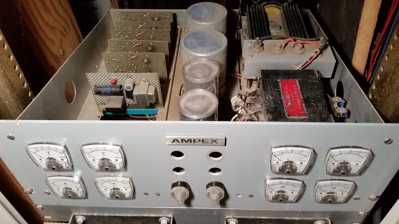
Post some pics if you can, so others can learn form your project.
An externally hosted image should be here but it was not working when we last tested it.
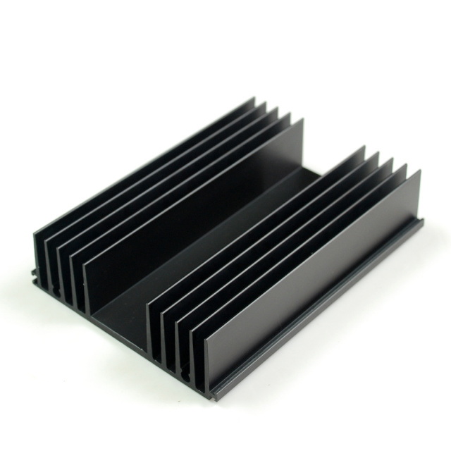
Aluminum cooling heat sink, SUNeMALL.com, DIY audio, heat sinks, heat sink, heatsink, heatsinks, Aluminum heat sink, cooling, cooling products, extruded,
Mounting a transistor (2N3055) to heatsink
Last edited:
Thanku Andrew ---you,re quite right --NOW I know what type transformer to
import from the IST world suppliers---so 15 volt ac out---will give me 20 volt-3-5amps ? DC( I assume that current is what the TDA 2040 requires( under max fx unit
preamp power output)--- but again --I am no expert --just love building amps
--so I wait 2 months for a suitable transformer ---(and then try to bribe a moronic stern bent customs dude --who thinks I may be constructing a bomb !)
agh well those who lived here know exactly the officialdom cretins who rule white minority--)
maybe better to search an old scrap tv or amp for a 220 --15volt transformer-
like AJT said ----we do not throw anything away--
( there is a 140 watt TDA amp module that uses 40 volt DC)--- one daymaybe get the courage to tackle it!( has an enormous heat sink --that is live!)--nasty idea--
thanku Andrew T --REALLY appreciate the highlander info --
and am grateful to AJT --- ( someone is on my side)
not all of us are geniuses --simply asking for help /advice does attract the supremacist gods on this forum --to punish the not-so -clever laymen for
daring to ask what they perceive as dumb questions---
never mind --there are many superb Samaritans here who have my utmost respect
thanku all
Last edited:
by the way ---the PC LAPTOP 19 volt dc supply ----works pretty well
ok --on the TDA 2040 AMP ---- there is a bit of noise /oscillation --but faint
-only on guitar overdrive FX pedal setting ---
well done the British ---! simple solution to a long painful dilemma --
thanku so much !
ok --on the TDA 2040 AMP ---- there is a bit of noise /oscillation --but faint
-only on guitar overdrive FX pedal setting ---
well done the British ---! simple solution to a long painful dilemma --
thanku so much !
Hi WSJ ---
forgive the dumb question---
trying to post a foto for you ---downsized to aprox 750 kb,s
as a PC novice ---how did u get those schematics posted ? I don,t see a "attach icon or paperclip icon to click on ? is this now to become another mission just to show you my circuit so far ?--- please show a shortcut ---soon as a URL or http is mentioned ----I run for cover---
thanks
Upload you pic to the Gallery. Then right click on pic, left click on Properties, cut URL and paste in Forum, with the insert image icon.
This is a regulator with current limit. I designed this PCB in 1968, it has been working great for 46 years.

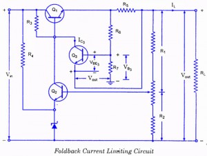
This is a regulator with current limit. I designed this PCB in 1968, it has been working great for 46 years.
An externally hosted image should be here but it was not working when we last tested it.
Last edited:
Upload you pic to the Gallery. Then right click on pic, left click on Properties, cut URL and paste in Forum, with the insert image icon.
This is a regulator with current limit. I designed this PCB in 1968, it has been working great for 46 years.
LOVED the taped PCBs .
I also started over 40 years ago and way back then, Bishop Graphics "precision slit" black crêpe tape and self adhesive pads was the "hi tech" preferred way to go.
Thanks for reviving lost memories
- Status
- This old topic is closed. If you want to reopen this topic, contact a moderator using the "Report Post" button.
- Home
- Amplifiers
- Power Supplies
- Simple 20 volt DC from 220 AC circuit