Kastor- yes, I tested some Teflon aircraft coax. Fantastic stuff on the waveform, also has a dissipation factor of 0.00002, though moderately high capacitance.
Is it a perfect looking square-wave with a little peak at the edges?

I think I mentioned that, as mica caps are the example always used for very low DF with surprisingly high DA. It's true, but that "high" DA is in comparison with better dielectrics and my guess is it isn't even on the map compared to the stuff they make cables out of, with the exception of Teflon. Or, maybe it only shows up in a different frequency range. I don't know if DA is entirely predictable once you have a single point measured. When I get back to the scope I'm going to add an air variable cap to the other input. Then I can null the square wave, increase the gain, and see much more subtle differences. My guess is I'll be able to see the DA of the mica cap then. I need to find a similar value NP0 to compare- I have about 8 billion components here, but never the right values! Have you ever seen a 68000 pF silver-mica? I have one. 270 pF or similar NP0? Not a one!
The reason I like differential measurements so much is they show errors regardless of cause, then the fun is explaining them.
Have you ever seen a 68000 pF silver-mica?
RFMICROWAVE | CMA-6N8 | Horizontal silver mica capacitor 68 nF 5%
It won't work that way, because the vertical channels saturate at ~200% of the full scale deviation, and with a 5mV/div setting, the stimulus couldn't exceed 100mV very much which would be mostly useless, but fortunately there is an even simpler way: just put resistor between one input and the ground, and feed your generator through the DUT.BTW, anybody with a scope can, and should, duplicate this test. Almost all two channel scopes will let you invert one channel and then sum them (A+B mode), giving you a differential amplifier. Find a couple matched resistors, a function generator and Bob's your uncle.
Basically, you create a differentiator of which the DUT is the reactive element.
The inconvenient of this arrangement is that no side of the DUT will be grounded, but this shouldn't be a problem since generators have a low output impedance, typically 50 ohm.
Regarding the results, they may look spectacular (and some spectacularly bad), but in fact they aren't:
Firstly, what we see is a purely linear effect: it has no impact on linearity. It is a component of the dielectric losses. You can call it dielectric absorption, or something else, it doesn't really matter: DF and DA are no two different things, DA is just a component of the DF expressed in a convenient form.
DA is not limited to long time constants: it comes under various forms. In french, one of them is called "traînage", I think the translation could be "streaking".
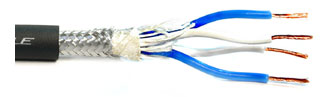
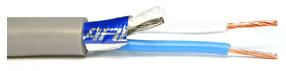
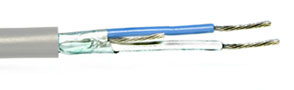
This type of phenomenon is typical of heterogeneous materials or cable construction: it could be due to a particular filler of the polymer, or to multiple materials in the cable: wire insulation, strands of textile as fillers, strands of polymers for mechanical resistance, overall insulating wrap, foil shielding:
An externally hosted image should be here but it was not working when we last tested it.
Chances are that low-microphonic cables are particularly "bad" in this respect...
Secondly, the effect is not only very small, but to have any impact, it would require large source impedances, and even then it would manifest itself as variations in the gain vs frequency smaller than for a "good" cable of similar capacitance.
Thirdly, the characteristic impedance of cables (even the very best ones) at audio frequencies is nowhere near "clean": the argument of the impedance is close to -45° and variable with frequency, and the magnitude also varies with frequency
Elvee, I'm afraid you're right about scopes. The common mode range isn't great enough, unlike the dedicated differential plug-ins. There are some op-amp circuits with huge common mode range (an ancient National app note comes to mind) but there may be a noise price with the large values they use. Still, if somebody were interested enough, they could make an op-amp diff amp for the test.
As for the rest, I feel somewhat like the blind man trying to describe an elephant by the feel of its leg. I simply don't have enough knowledge about how some of the parameters interact.
DF and DA are certainly related, but I'm not convinced they're always the same thing. DF is an energy loss- for every cycle you get back a little less than put in, and the difference is dissipated as heat. DA, or "soakage", doesn't necessarily imply that you don't get the energy back, it just takes more time. OTOH, DA is modeled using multiple RCs in addition to the main one, so maybe the loss is real for that too.
The problem with trying to model any of this stuff is that standard cap models are only good for a single frequency. In the same manner I can null a capacitance bridge on a high DF and DA part at a single frequency with no problem. DF is frequency sensitive, so the bridge balance will change with frequency. That's also the flaw in the Jung capacitor null test- the DF couldn't be nulled out over frequency.
I don't understand how you can say the error is linear. If it were linear or proportional the square wave would simply have some tilt, but never the form shown with the "bad" cables. I do agree these effects are not huge, but at the same time, something must account for different sounding interconnects. Unless there are no different sounding interconnects! I'm pretty sure I can round up two groups, believers and not, just as it's been for decades! Heck, we were arguing about this back when I was in college in the '70s.
Regardless of the magnitude, audibility and reasons behind it, the test does show the difference between the signal that should have arrived, and the signal that really did. Given a choice, I'd go with cables having less error.
Interestingly, the Monster cable has the most complex construction, with twisted fibers and the conductor wound around a clear plastic core, and performs well (because of it, or in spite of it) and the "bad" cable has the most basic coax construction, with a single simple dielectric.
The differential input test is the same as was in the AudioXpress article 11/09 Distortion meter. There the readout was using an AP System 2 FFT and a custom built differential input and a two tone low level signal. Now to trade cables and see if the results track.
There have been others who also have looked across the cable to see what happens.
There have been others who also have looked across the cable to see what happens.
You are right: they aren't exactly the same thing: DA is included in DF (or cos φ and similar global parameters), but it doesn't include parameters like the actual series resistance (not the ESR, which is also global)DF and DA are certainly related, but I'm not convinced they're always the same thing.
No, the process does imply a loss: if you charge any capacitor through any resistor (or resistive-like process), you have to invest an energy equal to CV² to recover CV²/2 at best. Since in this case the processes of charging and discharging will both create losses, things will be worst.DF is an energy loss- for every cycle you get back a little less than put in, and the difference is dissipated as heat. DA, or "soakage", doesn't necessarily imply that you don't get the energy back,
Yes, and that model is useful for another reason: it shows that there are an infinite number of time-constants, ranging from the highest (generally classed under DA denomination) to shorter ones (dielectric losses in general)OTOH, DA is modeled using multiple RCs in addition to the main one, so maybe the loss is real for that too.
The problem is that the ε of the dielectric is not a simple arithmetic value, but a complex number. If that is taken into account, most of the difficulties disappear (factors like the ohmic resistance remain)The problem with trying to model any of this stuff is that standard cap models are only good for a single frequency. In the same manner I can null a capacitance bridge on a high DF and DA part at a single frequency with no problem. DF is frequency sensitive, so the bridge balance will change with frequency. That's also the flaw in the Jung capacitor null test- the DF couldn't be nulled out over frequency.
It is linear in the usual meaning of the term: the relation between the input and output amplitudes is constant, ie it does not generate harmonic or intermodulation distortion. It only changes the amplitude/phase vs frequency response.I don't understand how you can say the error is linear. If it were linear or proportional the square wave would simply have some tilt, but never the form shown with the "bad" cables.
If you use a pure sinewave instead of a triangle, you will (almost) not find other frequencies in what you measure
That is a completely different debate....I do agree these effects are not huge, but at the same time, something must account for different sounding interconnects. Unless there are no different sounding interconnects! I'm pretty sure I can round up two groups, believers and not, just as it's been for decades! Heck, we were arguing about this back when I was in college in the '70s.
I am not sure about your exact test configuration: did the signal actually pass through the DUT? (I don't think so) A schematic would help.Regardless of the magnitude, audibility and reasons behind it, the test does show the difference between the signal that should have arrived, and the signal that really did. Given a choice, I'd go with cables having less error.
If the signal actually passed through the DUT, then what you consider as "bad" cables are actually the best, because for a given capacitance they give the less average error
Quite surprising, unless of course the dielectric of the bad cable is not the usual PE or PTFE stuff of coaxials but some spiked PVC or similarInterestingly, the Monster cable has the most complex construction, with twisted fibers and the conductor wound around a clear plastic core, and performs well (because of it, or in spite of it) and the "bad" cable has the most basic coax construction, with a single simple dielectric.
///
It is linear in the usual meaning of the term: the relation between the input and output amplitudes is constant, ie it does not generate harmonic or intermodulation distortion. It only changes the amplitude/phase vs frequency response.
The cable difference looks like it's affecting the transient response, not amplitude or frequency response.
It's like an amplifier, all perfectly flat with varying transient response, at least that's what it looks like in this case, since the DA transition is causing a non-uniform electron displacement.
The cable difference looks like it's affecting the transient response, not amplitude or frequency response.
You apparently haven't taken the suggestion from numerous people to learn the basics of Fourier analysis.
It's like an amplifier, all perfectly flat with varying transient response, at least that's what it looks like in this case, since the DA transition is causing a non-uniform electron displacement.
This is gibberish.
The Jung Capacitor test still holds up. We were testing for differences, not hoping for a perfect null. When the DA is low, the null is almost perfect.
It's not a bad test, though I don't remember what the conclusion about various different caps was. The problem, in my mind anyway, is that once the reactance is large enough not to influence the audio, what else is there? DF and DA. A single resistance can't null them perfectly over a wide frequency range, so the comparison isn't definitive. Now, if the reactance is large enough, and if DF and DA are very low, I don't believe there will be detectable sonic differences, perfectly nulled or not.
OTOH, here I am suggesting that small differences in capacitance properties of cables are audible. Oh heck, a foolish consistency is the hobgoblin of little minds...
After some more measurements, I think I'm going to be content to just lump everything under "losses" and call it a day. Separating DF and DA remains a bit of a mystery to me, and the end result is all that matters.
Measuring the "bad" cable at levels from a few mV to 20 Vrms (1 kHz) showed no change in capacitance or DF. Measuring it from 20 Hz to 500 kHz at a fixed level, it showed a substantial change in capacitance. That's probably a clue that it suffers from DA, and the "good" cables didn't do that.
Adding an air variable capacitor to the other input is starting to turn the test into a bridge, but it can also easily confuse matters because it can flip the waveform shape, making the result look like overshoot. It does allow turning up the gain even further to see differences between the better dielectrics.
Not surprisingly, the Teflon aircraft coax nulls flawlessly, with no visible residual at all. Nothing else was quite that good. It's also nice to have a really bad cable to test because I can also hear it. I doubt any difference between the low loss cables is detectable, at least to me.
Capacitors can also have significant inductance and vibration (high Q) sensitivity.
We found that when you made caps with polystyrene, polypropylene, and Teflon, there is little difference in measured DA, but even a teflon cap or wire, might not sound very good, as would be expected It was quite a surprise for me (30 years ago).
We found that when you made caps with polystyrene, polypropylene, and Teflon, there is little difference in measured DA, but even a teflon cap or wire, might not sound very good, as would be expected It was quite a surprise for me (30 years ago).
The "flawless" cable is also the one that will perform worst in terms of audio interconnect: it will give an unadulterated rolloff up to very high frequencies, act as a comb filter at certain frequencies, etcNot surprisingly, the Teflon aircraft coax nulls flawlessly, with no visible residual at all. Nothing else was quite that good. It's also nice to have a really bad cable to test because I can also hear it. I doubt any difference between the low loss cables is detectable, at least to me.
Imperfection is sometimes a virtue when accuracy is required: after all, oscilloscope probe cables are among the lossiest you can find, yet they are required for a perfectly flat response from DC to hundreds of MHz.
Something worth meditating about....
You apparently haven't taken the suggestion from numerous people to learn the basics of Fourier analysis.
I'm well aware of the strict relationship between frequency and time.
When I adjust the volume dial on an amplifier, that doesn't affect time, however.
Not surprisingly, the Teflon aircraft coax nulls flawlessly, with no visible residual at all. Nothing else was quite that good.
It would be nice to see someone repeat the Nelson Pass 5 uS impulse response tests on cables.
I can see thousands of pdf's viewing the impulse response in amplifiers and a single pdf viewing it in cables.
Not sure what the difference is to deserve this deviation.
The "flawless" cable is also the one that will perform worst in terms of audio interconnect: it will give an unadulterated rolloff up to very high frequencies, act as a comb filter at certain frequencies, etc
Imperfection is sometimes a virtue when accuracy is required: after all, oscilloscope probe cables are among the lossiest you can find, yet they are required for a perfectly flat response from DC to hundreds of MHz.
Something worth meditating about....
That's a very disturbing statement and meditating will definitely be required!
IMO, at least at this second in time, none of those effects should be happening at audio frequencies, and the rest of the system should insure that the cables are not being excited at frequencies where we have to abandon lumped time constants or worry about transmission lines, except in terms of unwanted external EMI.
I'm well aware of the strict relationship between frequency and time.
Apparently not, despite your nonsequitur about the volume control.
"The cable difference looks like it's affecting the transient response, not amplitude or frequency response" is a statement that clearly shows that you have a lot of basics still to master.
Hello again,
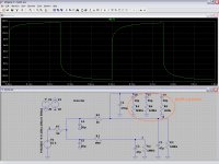
I modeled your measurements with lossy cables in LTSpice.
The result - after playing 5 minutes with the values is not perfect,
but it looks very similar to your bad cables (Picture is attached).
My personal conclusions are:
- The DA/DF capacitor model generates quite similar curves as you have measured.
- The DA/DF model is linear.
Even if the underlying effect is nonlinear,
it is so small that approximation by a linear model is valid.
- Simulating the frequency response does not reveal anything to worry about
The DA/DF capacitor model brings some light in the difference between DF and DA:
If you measure DF you measure the R
If you measure DA you measure the time constant R-C
Adding small inductors (1uH) does not change anything at audio frequencies.
Attachments
- Status
- This old topic is closed. If you want to reopen this topic, contact a moderator using the "Report Post" button.
- Home
- Source & Line
- Analog Line Level
- Low level interconnect (RCA) measurements