Hi, I am interested in the shielded box, do you have a part number?, I see WE stamped, which i assume is Worth Electronics? I have used some of their parts on other projects. I will use it for an RF design I am doing using a Si4770 chip. In order to primarily shield for the AM/MW freq band.
I had to get my LS389B duals from a group in Florida. Still have to see if I can get some matched pairs using BF862 to see if they are suitable, but will make a dual footprint in order to use either.
Thanks
Rick
I had to get my LS389B duals from a group in Florida. Still have to see if I can get some matched pairs using BF862 to see if they are suitable, but will make a dual footprint in order to use either.
Thanks
Rick
Hi Rick,
Yes, the shielded frame and cover are from Wuerth Elektronik, see:
WE-SHC Shielding Cabinet - Product Catalog Passive Components
You can source them from Digikey with P/Ns:
732-2493-ND
732-2494-ND
I hope this helps.
Best regards
Giorgio
Yes, the shielded frame and cover are from Wuerth Elektronik, see:
WE-SHC Shielding Cabinet - Product Catalog Passive Components
You can source them from Digikey with P/Ns:
732-2493-ND
732-2494-ND
I hope this helps.
Best regards
Giorgio
A modeled harmonic spectrum of-130dB at ~10dB/4V 10kHz output is excellent. How well does it model at low frequencies like 10Hz and higher frequencies like 50kHz and square wave at 100kHz? I ask because I have found that low frequency signals, be them source noise or part of the recording, can cause non-linearities to introduce products that make their presence known. As for high frequency testing, I am just curious. I usually aim for a half-power bandwidth 5 times my target frequency. Your design looks good. I've been working on a discrete design that I might post later. It needs some tweaking but might be worth posting.*Bump* - Another set of improvements, this time to the venerable Melcor 1731:
1) Added LTP CCS - many pros and cons, but it reduces THD20.
2) Added LTP Current Mirror - requires some care because of the differential VAS.
3) Added VAS Cascode - tried a lot of arrangements, but ultimately it is deceptively simple. If you look carefully, this is equivalent to the VAS cascode in the SWOPA, but with transistors rather than diodes (one transistor is diode-connected).
4) Re-biased the VAS to keep the VAS currents roughly the same as the LTP currents - this helps to keep the LTP collector loads roughly balanced.
Overall, it is more complex than the FET990, and does not reach the same level of simulated performance or sonics, but it uses mostly BJTs (can be made 100% BJT by using a BJT doublet for the LTP CCS). Four pairs of these can be implemented with (matched) BJT duals.
Simulated THD20 at 4V into 600R is a very respectable -130 dBr. It does pretty good at fairly high swings as well, right up to the onset of clipping. Further simulation is needed to check the overload and clipping behaviour - it may require clamp diodes like the FET990.
Last edited:
A modeled harmonic spectrum of-130dB at ~10dB/4V 10kHz output is excellent. How well does it model at low frequencies like 10Hz and higher frequencies like 50kHz and square wave at 100kHz? I ask because I have found that low frequency signals, be them source noise or part of the recording, can cause non-linearities to introduce products that make their presence known. As for high frequency testing, I am just curious. I usually aim for a half-power bandwidth 5 times my target frequency. Your design looks good. I've been working on a discrete design that I might post later. It needs some tweaking but might be worth posting.
It hasn't been simulated extensively at any frequency other than 20 kHz - I'll get around to doing all that after checking out clipping, overload, and all the other pathological stuff. If it cannot (or be modified to) handle all the corner cases, I'll just put it on the shelf as a curiosity (for future reference) and move on to other ideas.
Please post your topology (you can remove some circuit elaborations if you don't want to reveal everything) - a lot of the improvements on this thread have happened by mixing and matching ideas from different designs, some of which are over 50 years old.
Thanks for your invite here. The 2SK389 could likely be substituted with two instances of 2SK170's. I have removed a few portions, including the part of the correction stage that monitors offset/transient faults, and would monitor the output of a separate power amplifier. I'm sure it can be worked around. On the input there is a 20k potentiometer followed by a 470 resistor, then a mute circuit. From there, the signal enters the operational amplifier and SEPP stage, then passes by the correction stage. Let me know if you can work with this predriver/linestage. I hope it sparks an idea.

... I hope it sparks an idea.
Thanks, there are numerous novel (to me at least) ideas in your circuit. At first glance, the things that jumped out are the use of a baxandall super-pair as the VAS (though it's been explored in the FET990 variants on this thread earlier), with the novel biasing arrangement for the LTP FETs in conjunction with the PNP of the VAS super-pair.
It looks workable to mix-and-match a SWOPA-derived cascoded VAS with the LTP/VAS biasing ideas in this circuit.
Edit: I'd probably go with a Self Type II EF for the output, i.e. D6, D7 & D8 unconnected to the output.
Last edited:
It is workable from my preliminary simulations, but a bit of a bear to stabilize at unity gain - it looks like the relatively large C2 is needed, no easy way to lower its value. The large degeneration resistors (R13, R18) for the input JFETs are also unusual - perhaps the degeneration should be split between the JFETs and the inner PNPs to regain some bandwidth.
I re-installed ltspice some time last year. In doing so, I lost my Jfet and semiconductor library, preventing me from now seeing how well the circuit modeled when I last left it. Since then I dragged and dropped in a tube library which worked excellent, but that isn't helpful here. I recall this discrete had good low-frequency response extension (with a slight tilt toward higher frequencies, possibly less than a decibel), low noise, and low distortion. I wish I could run some tests right now and adjust it to suit.
The SMT parts make it all possible. with the lates 0201's and even smaller you have no limits in the number of parts you can use. Just that they can't be assembled by human hands. I was shown some resistors going into a project. They were indistinguishable from ground pepper.
You could use through hole parts in cordwood construction to get the volume smaller.
You could use through hole parts in cordwood construction to get the volume smaller.
Attachments
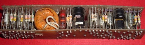
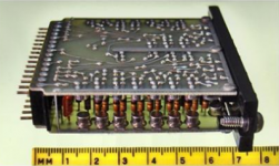
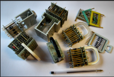
I've seen these kinds of modules before, but had no idea they were called cordwood construction - these were used in '60s solid-state equipment. It would be a bit messy to do the layout using present-day layout tools like Eagle, because parts span two boards.
I do use vertically-placed through-hole resistors in some designs, but with one lead bent into a U and both leads soldered on the same board. In some cases, I use mezzanine construction with two boards, but the only components that span the boards are mechanical struts with no electrical connectivity between the boards - I use edge connectors and an additional base board, when needed, for connectivity between boards.
I do use vertically-placed through-hole resistors in some designs, but with one lead bent into a U and both leads soldered on the same board. In some cases, I use mezzanine construction with two boards, but the only components that span the boards are mechanical struts with no electrical connectivity between the boards - I use edge connectors and an additional base board, when needed, for connectivity between boards.
Last edited:
So what is the point of posting a circuit design that "can not be assembled by human hands" in a DIY forum?The SMT parts make it all possible. with the lates 0201's and even smaller you have no limits in the number of parts you can use. Just that they can't be assembled by human hands. I was shown some resistors going into a project. They were indistinguishable from ground pepper.
You could use through hole parts in cordwood construction to get the volume smaller.
I can do SMT work, but it is slower to build. My concern with such small traces and solder joints is that it's so much easier for a joint fracture to occur as the device ages. Larger through-hole board designs that are complete with lead-based solder will last a lifetime. Cordwood introduces a concern for my own use; that method makes it more difficult to change out parts after it is assembled. It reminds me of the parts we were using at a plant where I was contracted a few years ago. The products were not designed to be repaired or dissassembled, and thus, any put through rework had to be completelystripped just to diagnose one component that was introducing the fault.
For a DIY design I would not use anything smaller than 0603. With some practice and patience (and a microscope!) they are not hard to place. Through hole are somewhat easier to build but really take a lot more real estate. The cordwood idea is for the really committed (in more ways than one). I did deal with them at Control Data and its great when money is not an object but no longer. Don't even try that if you have an option.
Stability: I was referring to unity-gain stability, since these are discrete opamps which we'd like to use (without compensation changes) for a wide range of applications, including buffers.
For dedicated unity-gain buffers, I did post link(s) to a few topologies at various places in the thread. There's one of mine that requires 2 BJTs and 2 JFETs, and another by Ken Peter posted elsewhere that can be implemented with 6 BJTs (maybe 4, with higher distortion). There's also another by Ken Peter that uses Schottky-switched crossover which can be done with 4 BJTs and 2 Schottky diodes.
For dedicated unity-gain buffers, I did post link(s) to a few topologies at various places in the thread. There's one of mine that requires 2 BJTs and 2 JFETs, and another by Ken Peter posted elsewhere that can be implemented with 6 BJTs (maybe 4, with higher distortion). There's also another by Ken Peter that uses Schottky-switched crossover which can be done with 4 BJTs and 2 Schottky diodes.
Just for fun..
http://www.johnhardyco.com/pdf/990.pdf
Reminds me of the old philbrick nexus..Teledyne
Is this the same one?
https://www.google.co.uk/?gws_rd=ssl#q=discrete+op+amp+kit
I have no connection its just for interest..DIY990..
Regards
M.Gregg
http://www.johnhardyco.com/pdf/990.pdf
Reminds me of the old philbrick nexus..Teledyne
Is this the same one?
https://www.google.co.uk/?gws_rd=ssl#q=discrete+op+amp+kit
I have no connection its just for interest..DIY990..
Regards
M.Gregg
Last edited:
- Home
- Source & Line
- Analog Line Level
- Discrete Opamp Open Design