First post. I am listening to a set of MTM speakers at the moment that have a flat baffle/not stepped or offset. I know the crossovers are simple cap and coil. With my simple take I can not understand how time alignment is achieved. I also get some of the issues, like the acoustic centers changing with frequency.
I would really like to keep these, but I also want to understand them and be comfortable with the designer’s ideas.
I know this is a can of worms, and have read many contradictory and authoritive takes on the subject.
Thanks in advance.
An externally hosted image should be here but it was not working when we last tested it.
An externally hosted image should be here but it was not working when we last tested it.
I would really like to keep these, but I also want to understand them and be comfortable with the designer’s ideas.
I know this is a can of worms, and have read many contradictory and authoritive takes on the subject.
Thanks in advance.
Time alignment is not automatically required for a reasonable sounding loudspeaker. Preferable of course, if it's practical to achieve under a given set of design criteria, especially for low-order filters / acoustic slopes. However, acoustic slopes are rarely the same as the electrical, and higher order acoustical slopes are less sensitive to such issues given the reduced frequency overlap / narrower transition BW. You'd be going some to achieve that with a simple cap & coil, so very much depends on the drive units, baffle dimensions & driver locations on this, the XO values, & what other components (presumably there are some) are present. So we'd need details of these before being able to say much more. From the picture, they look to be from the Seas Prestige range (?).
Last edited:
Time alignment is not automatically required for a reasonable sounding loudspeaker. Preferable of course, if it's practical to achieve under a given set of design criteria, but I can think of plenty of decent enough speakers that are not especially well time-coherent.
Be that as it may, recall also that acoustic slopes are usually not the same as the electrical, which will affect the relative audibility of such matters, higher order acoustical slopes being less sensitive given the reduced frequency overlap / narrower transition BW.
Thanks. This is just me trying to square the designer's statements against the physical reality. These are not steep slope, high-order crossovers. I also get that time alignment is a nice design goal, but may not pan out in real world listening. Still, having lived with Vandersteens for 20 years; I struggle with the how of the design, wanting to understand.
Could a series crossover impose a frequency-dependent delay? Could the use of both acoustic suspension and transmission line designs be part of the solution?
I am looking to this forum and its smart guys and galls to help on this one.
The time delays are caused by the acoustical slopes, series or parallel does not matter. If you want to delay the tweeter then you have to use a lattice filter which isn't easy to just conjure unless you use simulations.
In the end I'd measure and see if it is a problem in the first place, and if not I'd let it be. If it is a problem I'd just buy some cheap and nice DSP and solve the problem that way. You could even get FIR capable DSP and make the transient response perfect thus making the speaker linear phase when you are at it.
In the end I'd measure and see if it is a problem in the first place, and if not I'd let it be. If it is a problem I'd just buy some cheap and nice DSP and solve the problem that way. You could even get FIR capable DSP and make the transient response perfect thus making the speaker linear phase when you are at it.
The crossover's slopes do not impart time alignment. The impulse alignment of the low and high frequency drivers is far off. What the crossover does offer is approximate phase coherence where the drivers meet, at least enough to prevent cancellation. If you want time alignment then you have the choice of active correction or altering the physical placement of the drivers. Using an acoustic measurement system with the crossovers removed and a steady stream of low-level impulses fed to both drivers, use the scope function to visually align them. From there, design the crossovers to retain the phase alignment, or take it further to design a linear phase coherent system with minimal lobing. I avoid MTM arrangments due to their problematic vertical dispersion.
Thanks. This is just me trying to square the designer's statements against the physical reality. These are not steep slope, high-order crossovers.
Possibly not, but since you're not telling us anything we need to know, we can't help much, or establish what they're actually doing, so this is all pure guesswork. To do more, as said, we need to know:
-The drive units
-The filter topology and values (all components)
-The baffle dimensions
-The exact location of the drivers on the baffle.
As noted, in practice, your cap & coil 1st order electrical filter may actually be a higher order acoustical. Especially if there are other components present in the filter. Higher order acoustical slopes are (generally) less sensitive to time-delay misalignments et al.
Could a series crossover impose a frequency-dependent delay?
No. Not unless you incorporate some form of delay, which would be much more practical with a parallel filter.
Could the use of both acoustic suspension and transmission line designs be part of the solution?
Not in time-aligning a speaker through the XO transition band. As an aside, I can't quite see how you can combine acoustic suspension with TL loading for the same drive unit. It's either one or the other, not both (with the arguable exception of a rather undersized sealed TL).
Last edited:
Possibly not, but since you're not telling us anything we need to know, we can't help much, or establish what they're actually doing, so this is all pure guesswork. To do more, as said, we need to know:
-The drive units
-The filter topology and values (all components)
-The baffle dimensions
-The exact location of the drivers on the baffle.
As noted, in practice, your cap & coil 1st order electrical filter may actually be a higher order acoustical. Especially if there are other components present in the filter. Higher order acoustical slopes are (generally) less sensitive to time-delay misalignments et al.
The designer is not forthcoming with so many details.
The drive units are SEAS, but the mid/woof at least is custom. The tweeter is SEAS as well. No idea on the topology, save that one mylar cap and an inductor are used. The designer says the mylar cap is mandatory and that more exotic caps are used on other speakers but will not work with this design. The dimensions are 7.5 wide, 16 deep, 24 high.
I totally agree that a transmission line and acoustic suspension are at odds. I agree about the time alignment, thus my post. There are obviously design parameters that don’t add up, and if I can’t sort it out, I may return them as I know myself and I will be bothered by the cognitive dissonance.
The tweeter is centered 14" from the base of the cab, with a 4" diameter and the 6.4" mid/woofs are less than a 1/4" top and bottom.
I avoid MTM arrangments due to their problematic vertical dispersion.
This is my first time around with MTM. I find the vertical dispersion better than my Vandys. The off axis response and dispersion were what I wanted to test in my actual room.
It's very possible that the lobing occurs in a narrow angle window. I find, however, that a TMW arrangement allows me to completely remove the lobing from listening angles that would be associated with standing, and sitting. With the MTM, there is an attenuation lobe below and above the on-axis angle. Of course, if all the listening is done while seated, then there is no problem at all.
The designer is not forthcoming with so many details.
This is a commercial speaker then? Where from? Unless you're willing to measure the drivers (FR + impedance) & open the box sufficiently to check the components in the filter, nothing we can do.
The drive units are SEAS, but the mid/woof at least is custom.
As above. Without any information, we can't say much.
The tweeter is SEAS as well.
Ditto, since we need a model number.
No idea on the topology, save that one mylar cap and an inductor are used.
So just those -no other components at all? Without knowing their values along with the aforementioned re the drivers, again, nothing we can contribute. This is DIY after all, so some element of that will be needed.
The designer says the mylar cap is mandatory and that more exotic caps are used on other speakers but will not work with this design.
Mylar (polyester) caps are generally viewed as 'inferior' to polypropylene in outright technical performance, which is generally true, if a bit over-simplistic. There are differences that can have an impact, e.g. the cap ESR for a given value. That can be incorporated into the filter design; it would need to be fairly high to alter things to a large extent though, and the difference between decent quality polyester and polypropylene caps in this regard usually isn't all that great. I wouldn't rule it out, but I rather suspect the case is being overstated.
The dimensions are 7.5 wide, 16 deep, 24 high... The tweeter is centred 14" from the base of the cab, with a 4" diameter and the 6.4" mid/woofs are less than a 1/4" top and bottom
Useful, but without the rest mentioned above, we're still just guessing unfortunately.
I totally agree that a transmission line and acoustic suspension are at odds. I agree about the time alignment, thus my post. There are obviously design parameters that don’t add up, and if I can’t sort it out, I may return them as I know myself and I will be bothered by the cognitive dissonance.
TL + AS on the same driver is an oxymoron, unless as noted the former is a (arguably undersized) sealed line. In which case, it's a TL. One or the other, not both. That aside, I wouldn't automatically say the design parameters in general don't add up, but we don't know the drivers, the filter values or any other components present, nor have we the original manufacturer's text to work on, and without any of this, there's little we can say or do to analyse the speaker & its behaviour. Sorry.
First post. I am listening to a set of MTM speakers at the moment that have a flat baffle/not stepped or offset. I know the crossovers are simple cap and coil. With my simple take I can not understand how time alignment is achieved.
Thanks in advance.
Looking at your system we can see that the drivers are mounted on a common baffle. This guarantees that the deeper woofer units will have their acoustic centers farther back than the acoustic center of the tweeter. For the most part the acoustic centers will be at the depth of the voice coils, at least for frequencies in the center of their respective pass bands.
A simple crossover can not correct this and their will always be relative delay in the woofer's range. I don't know if the designer is claiming otherwise, or just unclear in his terminology. What you can do is control the crossover region and bring the phase response of the high and low sections into allignment. Generally more crossover slope will pull the woofer phase downwards and likewise pull the tweeter phase upwards. Usually some combination can be found that gets the section phases to match at the same slope, giving time alignment at the crossover frequency only.
Capacitor or inductor types have nothing to do with any of this. It is determined by crossover topology and parts values.
David
Speaker Dave, can time alignment be easily obtained in a 2-way application by simply tipping the speaker back 15 deg or so on an appropriately build stand w/o having to accomplish the TA in the xover?
Yes, tipping the system back until the acoustic centers line up (relative to the listener's position) will work. But most likely the crossover was optimized for 90 degrees from the baffle surface and the tilted back axis may give a hefty cancelation dip. In that case then tilting back and flipping tweeter polarity might get you to time alignment along with flat response.
Of course, with the symmetrical array of the OP's, this won't work, only with single woofer systems.
I did this years ago with a large Advent and it passed a reasonable square wave.
David
Last edited:
Yes, tipping the system back until the acoustic centers line up (relative to the listener's position) will work. But most likely the crossover was optimized for 90 degrees from the baffle surface and the tilted back axis may give a hefty cancelation dip. In that case then tilting back and flipping tweeter polarity might get you to time alignment along with flat response.
Of course, with the symmetrical array of the OP's, this won't work, only with single woofer systems.
I did this years ago with a large Advent and it passed a reasonable square wave.
David
Thank you sir!
Thanks for all the responses. I am reading up on ESR value in caps just for fun.
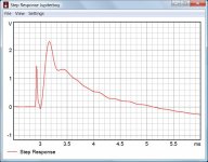
It strikes me that a good move would be to see if I could get a convincing step response from the speakers, which would indicate how well they perform in the time domain.
It also seems that acoustic centers of speakers are a slippery thing to pin down, and that time alignment may tend to help stabilize a stereo effect in a very particular, off axis area only, and be generally not correct in other listening positions. I note that some speaker makers stagger the tweeter in the horizontal plane, placing it further to the outside of the midrange drivers. It this is a valid design approach, then some time compensation would be acheived by virtue of the variance in radius between the midrange driver and the tweeter.
I notice this designer has a small box TM design that is also presented as time coherent. He also utilizes concentric drivers, so I suspect he is very aware of time alignment.
Maybe I'll have some luck measuring step response.
Eh? Not hardly, ESR = equivalent series resistance. I mentioned it purely in general terms since a good filter design takes the resistance of the components, be they resistors (!) inductors or capacitors into consideration, and they are often functional parts of the transfer function. For example, that's one reason why you need to be very careful when 'upgrading' a filter with, say, an inductor that has lower DC resistance than the original. Be that as it may, the relatively tiny amount of ESR on a series cap is not going to form a delay line to help time-align the drivers on this speaker. Would that life were so simple...
Last edited:
I assume the designer speaks of time coherence simply because first order filters theoretically yield a perfect step response. Of course he omits to mention that the practical implementation does not at all.")
It's thinkable that one woofer internally is in a sealed chamber and the other one in a transmission line. Whether that makes sense or not is another question.
The woofers seem to have transparent polycones and inverse surrounds, they look like Seas T17RE. The tweeter is hard to identify, there are so many Seas tweeters looking almost identical.
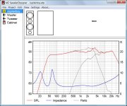
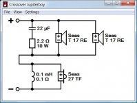
As we don't know what's really inside of the box, I made a simulation using a sample serial crossover. It's just a guess in order to find out what to expect...
It's quite possible to achieve a more or less flat frequency response on axis. However, crossover and phase are very poor in comparison to a decent design. Horizontal and vertical dispersion also are poor due to the wide overlap of shallow filters. If your speaker actually isn't significantly better than the simulation then I would be cautious regarding the marketing claims of the designer.
It's thinkable that one woofer internally is in a sealed chamber and the other one in a transmission line. Whether that makes sense or not is another question.
The woofers seem to have transparent polycones and inverse surrounds, they look like Seas T17RE. The tweeter is hard to identify, there are so many Seas tweeters looking almost identical.
As we don't know what's really inside of the box, I made a simulation using a sample serial crossover. It's just a guess in order to find out what to expect...
It's quite possible to achieve a more or less flat frequency response on axis. However, crossover and phase are very poor in comparison to a decent design. Horizontal and vertical dispersion also are poor due to the wide overlap of shallow filters. If your speaker actually isn't significantly better than the simulation then I would be cautious regarding the marketing claims of the designer.
Attachments
I assume the designer speaks of time coherence simply because first order filters theoretically yield a perfect step response. Of course he omits to mention that the practical implementation does not at all.
It's thinkable that one woofer internally is in a sealed chamber and the other one in a transmission line. Whether that makes sense or not is another question.
The woofers seem to have transparent polycones and inverse surrounds, they look like Seas T17RE. The tweeter is hard to identify, there are so many Seas tweeters looking almost identical.
As we don't know what's really inside of the box, I made a simulation using a sample serial crossover. It's just a guess in order to find out what to expect...
It's quite possible to achieve a more or less flat frequency response on axis. However, crossover and phase are very poor in comparison to a decent design. Horizontal and vertical dispersion also are poor due to the wide overlap of shallow filters. If your speaker actually isn't significantly better than the simulation then I would be cautious regarding the marketing claims of the designer.
Thanks so much for this. I am seeing that same 4K peak in this speaker’s frequency plot. I suppose you crossover has an additional resistor.
Part of my confusion, as a listener, is going from a Vandersteen 1B to this speaker—both two-way, first order, transmission line speakers. Both image very well, but have a narrow vertical window, these being more forgiving than the Vandys. I don’t want to fool myself into thinking that 4K hump is more detail. I also am detecting some oddness around 2K based on simple analysis of test tones from an old test record.
If my step response measurement looks anything like that, I do think I will be returning them. I’ll do my best at getting some measurements from the seating position next week and see how they look.
Again, thanks so much for the generous assistance. I tend to live with my purchases a very long time, so I want to be as careful as I can in making my decisions.
I am also noticing that this impedance curve drops to 3.5 ohms at two points, which corresponds to what the designer mentioned, if I recall.
Last edited:
- Status
- This old topic is closed. If you want to reopen this topic, contact a moderator using the "Report Post" button.
- Home
- Loudspeakers
- Multi-Way
- Cap and coil, time alignment with flat baffle.