A Good sound card and a free program such as REW, WaveSpectra or Visual Analyzer.
Holm Impulse is another great program but you have to convert the graphs from db to %.
See this thread,
http://www.diyaudio.com/forums/software-tools/256036-amplifier-measurements.html#post3925301
jer")
Holm Impulse is another great program but you have to convert the graphs from db to %.
See this thread,
http://www.diyaudio.com/forums/software-tools/256036-amplifier-measurements.html#post3925301
jer
Last edited:
I have never had any issues as long as you use a proper voltage divider and a opamp buffer into the sound card.
And of course avoid ground loops and understand them.
jer
P.S Also you must calibrate your levels, That can be tedious but it is not difficult to do.
And of course avoid ground loops and understand them.
jer
P.S Also you must calibrate your levels, That can be tedious but it is not difficult to do.
Last edited:
resistor divider with standard metal film types, proper power rating will have distortion well below -120 dB
external op amp buffer not really needed for the divider - we're not making a MegaOhm 'scope probe here - it can be <~1 kOhm out, few 10s of K for the upper R
and the PC audio inputs are already buffered internally
if you buy 1-2W metal film R you could even go down to a few 100 Ohms for the divider output
Some cards are buffered and some aren't.
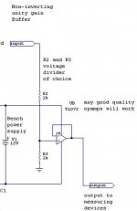
But, A high impedance unity gain buffer is required to isolate the changing input impedance of the input of the card.
This is typically caused due to the input capacitors changing impedance loading on the voltage divider in a non-linear fashion from the changing of the test frequency.
Every card and motherboard sound system that I have tested (that I have) has shown these types of error's.
Some show more than others and some not at all, YMMV.
Yes, as the lower you make the bottom resistor of the divider the lesser this input impedance error becomes.
The issue is that your margin of resistor tolerance becomes more difficult to get exactly perfect or better than .01% or .001%.
With a typical DMM you can measure 1001 ohms easier than you can measure 10.01 ohms.
FWIW
jer
Last edited:
Post your schematic of your buffer circuit to try,or better post the exactly setup schematicSome cards are buffered and some aren't.
But, A high impedance unity gain buffer is required to isolate the changing input impedance of the input of the card.
This is typically caused due to the input capacitors changing impedance loading on the voltage divider in a non-linear fashion from the changing of the test frequency.
Every card and motherboard sound system that I have tested (that I have) has shown these types of error's.
Some show more than others and some not at all, YMMV.
FWIW
jer
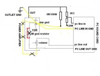
Mine is like this on photo.
Attachments
Last edited:
a buffer is needed at how low a level? do you see even -100dB with 1 kOhm source, maybe?
we are talking a cheap look with next to no cost, as I mentioned -80 dB is a fine goal for bettering 'scope and eyeball without buying a prosumer sound card like the Juli@
loopback with a same value R in series as the divider lower leg will let you see if there is a problem at the measurement levels you are interested in
there are lots of layers of onion peeling to get good measurements as you go deeper in resolution - but no reason to be paralyzed by not having the ultimate setup to start
Last edited:
Your setup of is fine except for having no buffer, and, mainly the ground loop that is caused by the use of both, the input ground and the output ground too the amplifier.
As long as your the Output cable from the sound card is shielded, The shield should only be connected on one end of the cable.
It doesn't matter which end just as long as only one end is connected.
jer
As long as your the Output cable from the sound card is shielded, The shield should only be connected on one end of the cable.
It doesn't matter which end just as long as only one end is connected.
jer
I tried it(one point gnd) but without good results.Your setup of is fine except for having no buffer, and, mainly the ground loop that is caused by the use of both, the input ground and the output ground too the amplifier.
As long as your the Output cable from the sound card is shielded, The shield should only be connected on one end of the cable.
It doesn't matter which end just as long as only one end is connected.
jer
All is ok when no load connected.I can measure THD 0.0022 THD+NOISE 0.0033
When load connected these are more bigger
BTW can you post a simple schematic of your setup?
Last edited:
JCX, I wish I had one of my orginal plots to show you but the margin of error was quite large without the buffer using motherboard sound system.
Thimios, if the amp is sharing the same earth ground as the computer through its power cord then it may be necessary to eliminate the ground connections from the amp to the sound card altogether.
I have also had to do this depending on how everything was being powered and from what circuit, as I have many things plugged in here and power ground loops are a big deal to make my system quiet.
Computer are notorious for these types of issues and it took me a long time to understand this and figure it out.
jer
usually i use ARTA for these measurements .Out voltage after divider is about 800 mVNow much bigger are your results.
What program are you using and has the level of your voltage changed when you hook up the load?
If it has then this changes your calibration.
Some programs do compensate for this and some don't.
jer
tl072 powered with single supply voltage?
Last edited:
many audio source have 100 Ohm resistors in series to isolate the amp from cable C load, I can't speak to every cheap PC motherboard sound system but I find it an odd claim that many would have "significant" error with such series R
I do know where to find fet input op amp distortion curves with source Z - and again as much as -80 dB is not expected with < ~1 kOhm source
audio inputs may also have their own ~ 100 Ohms in series in a input RF filter or current limit for the clipping diodes to the supply
to further debug measurements you should look at fft plots of the load data - do you see added line frequency components and line harmonics?
PC and amp should be powered from the same socket, certainly the same branch circuit
the RCA/TRS from the PC audio out to the amp must have the gnd continuous - don't cut the "shield" - it is the signal reference V
for difficult measurements - when the setup has gnd problems you could play back the test signal from a battery powered DAP/laptop/tablet... but do use .wav or lossless file type
if you have stereo line in (not computer "microphone" input) you could even get >30 dB gnd loop noise rejection with "pseudo differential" measurement - use both R,L sound channels with identical dividers, one to device gnd, and take the difference in between them (can calibrate for the resistor tolerance too)
for mid to high audio frequencies even cheap audio signal coupling/isolation transformers can break gnd loops and not add to the distortion - but cheap ones will distort near their lower frequency roll off
Last edited:
- Status
- This old topic is closed. If you want to reopen this topic, contact a moderator using the "Report Post" button.
- Home
- Amplifiers
- Solid State
- Cheapest way/kit to measure distortion?