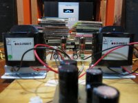
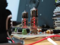
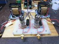
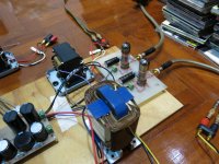
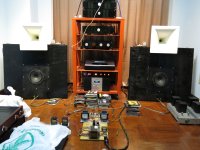
I just tried a very simple Amp with the 6E5P tube.
I have very efficient speakers, so I can life with around 1,2 Watts.
But the sound of this amp is so good, you would not believe.
Every detail is very clean and precious.
Even the bass have a good punch.
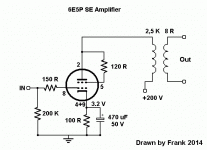
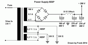
The schematics I will post later.
I have very efficient speakers, so I can life with around 1,2 Watts.
But the sound of this amp is so good, you would not believe.
Every detail is very clean and precious.
Even the bass have a good punch.
The schematics I will post later.
Attachments

I believe it. 6E5P is a wonderful tube. I use it as the driver in my 833C amps, and it's definitely as you describe.
Try biasing it with diodes - that will let you eliminate the cathode bypass cap. Four(4) Cree SiC schottky diodes (1A, 600V) will give you ~3.6V bias; you get about 0.9V per diode. I find that the diode bias gives even better bass!
Try biasing it with diodes - that will let you eliminate the cathode bypass cap. Four(4) Cree SiC schottky diodes (1A, 600V) will give you ~3.6V bias; you get about 0.9V per diode. I find that the diode bias gives even better bass!
Last edited:
I have it biased with yellow LEDs (2x2) for some 3.8V and sounds excellent.Try biasing it with diodes - that will let you eliminate the cathode bypass cap. Four(4) Cree SiC schottky diodes (1A, 600V) will give you ~3.6V bias; you get about 0.9V per diode. I find that the diode bias gives even better bass!
Nice!
I have 6E5P in front of GU50, an amplifier that I rebuild when the previous owner had not followed the rules for electrical safety.
I will try diodes too.
Anders
Is this SE or PP?
Hi Junm,
the tubes are electrical slightly different.
The output power is nearly same, 8,3 W to 8,25 W.
But beware, the pin outlet is totally different.
I think, if you use the 6E6P instead, and connect the pins right, the amp will working.
I do not have the 6E6P here, I like to order some 6E6P DRY tubes.
This tubes have gold pins and gold grid.
Here the scan of the pin outlet of both tubes.
Keep me informed, if your amp is running.
Attachments
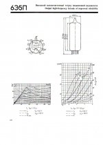
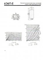
The 6E6P-E and -DRY have an plate resistance of 1.3K Ohm. 6E5P has 1K Ohm. 3.5-5K - OPT. Also the 6E6P has no intern connection of screen to cathode as 6E5P. You have to solder this extern with a piece of wire. Otherwise it won't sound good.
tubeman813: Lift the heaters to 50-60VDC. You'll be surprized about improvement.
I second Magz Cree sugestion. I am usual no fan of diode and LED bias, but the Cree silicium carbide diodes give you best HiFi and a magical tone.
Johann
tubeman813: Lift the heaters to 50-60VDC. You'll be surprized about improvement.
I second Magz Cree sugestion. I am usual no fan of diode and LED bias, but the Cree silicium carbide diodes give you best HiFi and a magical tone.
Johann
Member
Joined 2009
Paid Member
It means the heater is lifted positive with respect to the cathode. so you have a heater winding on your transformer, it gives 6.3V to the heater. then you connect one side (or centre tap) of the heater winding to +50V above cathode. the heater still only has 6.3V across it, but the whole heater sits +50V.
From the last psu cap, one resistor in serie(R1), then from R1 to ground a second resistor(R2). Across R2 you put a capacitor to ground, for decoupling. Ca. 22µF/300V to decouple it from the psu. Desolder the two 100R heater resistors from ground and connect to solder point R1/R2.
To not drop your B+ voltage use for R2 = 50K - 100K. Now multiply R2 with a value of 2.5 - 3 for R1 and you get 50V to 55V R1/R2. Some driver tubes sound better with elevated heater.
The Cree SiC would be also a upgrade for your diode bridge.
To not drop your B+ voltage use for R2 = 50K - 100K. Now multiply R2 with a value of 2.5 - 3 for R1 and you get 50V to 55V R1/R2. Some driver tubes sound better with elevated heater.
The Cree SiC would be also a upgrade for your diode bridge.
- Home
- Amplifiers
- Tubes / Valves
- Spud Amplifier with 6E5P Tube