One is PIN decoupling and one is Vref=2.5V decoupling.
I measured them some time ago and one is 100nF respectively 10nF.
Anyhow, I'll measure them again, just to be sure.
Regards,
Tibi
Measured and replaced.
Both are 100nF X5R bastards.
Highly temperature dependent. If you unsolder them and measure, their capacitance will jump to 160nF and slowly drop to near 100nF in half hour.
Now back to carefully listening.
Regards,
Tibi
Attachments

What temperature did you use to solder these in?
350°C Depending on your solder type it may be lower. I use SnAg alloy and for this you need higher temperature.
Regards,
Tibi
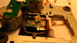
The WOOOOOW effect !!!!!
1nF silver-mica in PIN decoupling position. I got huge resolution and detail. I mean really huge. Super trouper mod !
Now optical focus is completely silent. Tracking is ultra fast. TOC reading is almost instantly.
At this stage, I wonder where SHIGA MKII stand now and if there are any near competitors.
Regards,
Tibi
Attachments
Now you have got my attention........this will be my second mod !!!!
You soldered one siver mica 1nF and left the other Vref XR in place ?
Can't beat that feeling of being the first he......!!!!!!!
Edit...at close look you soldered two silver micas 1nF I think
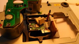
Both X5R bastards are removed and in the bin now.
Shiga MKII already have on PCB possibility to add a 1nF silver mica for 2.5V ref, therefore I left for Vref 100nF Arcotronics MKP.
For PIN amplifier decoupling I used an 1nF/100V silver-mica. This is the one who make a huge difference.
This cap changed everything, resolution, dynamics, speed etc. It's like I have installed a super clock.
With all these mods, now Shiga MKII it's so involving, like a very good vinil.
Best regards,
Tibi
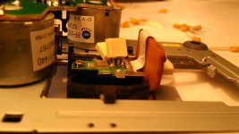
What's the glue you use to enclose the parts on that last photo?
Kind of silicon compound?
Silicon glue.
An externally hosted image should be here but it was not working when we last tested it.
Regards,
Tibi
Aah, nice and easy to use I believe?
Hold the stick near and warm it up so it drips in place?
Easy to use but better with a glue gun.
dadcando.com - Making: Pages packed full of wonderful, original and exciting craft projects, perfect for dads, mums and kids

Regards,
Tibi
Like this :
Danzup, hope you don't mind another question. I'm having trouble waking up my shiga and want to make sure I have all connections correct. The six point connectors are oriented by the terminals marked with '1'...correct? In other words, the '1' terminal on the board should connect to '1' terminal on the mechanism...right? Thanks. Kind regards.
Danzup, hope you don't mind another question. I'm having trouble waking up my shiga and want to make sure I have all connections correct. The six point connectors are oriented by the terminals marked with '1'...correct? In other words, the '1' terminal on the board should connect to '1' terminal on the mechanism...right? Thanks. Kind regards.
Six wire cable for motors is 1 to 1 - '1' terminal on the board should connect to '1' terminal on the mechanism.
If you followed this thread, than 3 wire cable for CD TOC reset is 1 to 3, 2 to 2 and 3 to 1.
Other things to check.
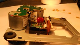
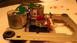
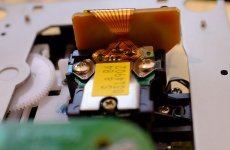
- optical ribbon cable connector do not be reverse soldered- see pictures in this thread
- remove laser protection bulb from CD mechanic
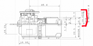
- distance between turntable and CD mechanic to be 19.4mm - see attachment
You may post here top and bottom high resolution pictures, so I may have a look.
Regards,
Tibi
Attachments
Last edited by a moderator:
- Home
- Source & Line
- Digital Source
- Shigaclone MKII Black - The builders Thread