Hi Juan,is any of these pcb already tested?well I use a copy layout from mister Willy because my printer was not getting a correct size, and there are many options from Willy that are really good he did, I also have a few for myself for later here are some imagesI tend to make a collection of my favorite layouts on this diy forums also B500 is one of my favorites too
the layout I use is the one with TO-3 transistors but I have plans for TO-3P or TO-264 packing
Regards
Juan
Last edited:
Hi Juan,is any of these pcb already tested?
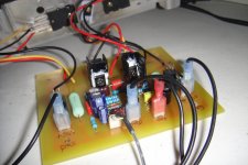
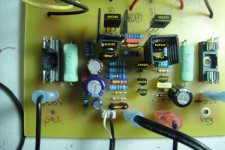
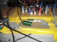
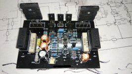
Only the one that mister Willy did, those other versions I have not tested yet but this one test it and all good here is the images, while I was listen to it I notice the main power transistors where getting a bit hotter so I thought because it does not have a zobel network then I add it a coil with a few turns with a 10 ohm 5W watts resistor and now is stable and nice and not and expert but I use what I learn from here
what slow me down on testing other boards is because I do not have to be honest good skills on etching boards I try the best I can and I love to see new designs here it does make me happy
Regards
Juan
Attachments
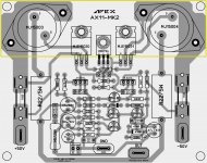
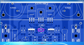
hello vargasmongo can i use 2sc5200 and 2sa1943 for Ax-11-MK2 pcb desing
yes those are the ones I'm using right now
also you can use MJL3281A - MJL1302A
Regards
Juan
Ok tq i will make new layout like mk-2 with 5200/1943yes those are the ones I'm using right now
also you can use MJL3281A - MJL1302A
Regards
Juan
PCB size is 7cm x 10cm
you mean this layout
dear sir
which type is relay you use there is no pole in relay?thanks
AX-11
If you gents could please share with me: What is the typical voltage gain of an AX11? also the typical bias?
p.s. I am planning on making bridged pairs with MJL output devices to handle bass/sub duty in a bi-amped system; so I would like to have an idea of how the gain will compare to the amps on top.
Thanks!
What is the typical voltage gain of an AX11?
If the input filter is arranged as on the original ax-11 schematic, with the 2k2 resistor directly in series with the input cap and before the 22k in parallel with the 330p cap, this makes a divider with a ratio of about 0.909 ( 22k/2k2+22k ).
Then the gain of the amp itself is 1+22k/2k2, with the 22k being the feedback resistor value and the 2k2 being the feedback shunt resistor going to ground via the 100u cap. This makes for a gain of 1+10=11 for the loop and the input divider brings this down to 0.909x11=10 or 20db ( 20xlog(10) ).
This is reduced near each end of the audio band by the roll off attenuation.

dear apex, which type of relay is used what is the number of relay that shop keeper says to me.thanksPCB size is 7cm x 10cm
you mean this layout
Last edited:
PCB size is 7cm x 10cm
you mean this layout
dear silheg
plz code number and size of relay which u use?thanks regard masood
dear silheg
plz code number and size of relay which u use?thanks regard masood
Masood,
use..OEN-54series,24v..orGoodsky..SH-224l
yes those are the ones I'm using right now
also you can use MJL3281A - MJL1302A
Regards
Juan
hello i have made this AX-11 but output voltage is too high 190milli volts
what to do?
Attachments
hello i have made this AX-11 but output voltage is too high 190milli volts
what to do?
are those original Toshiba power transistors bro
the voltage is too high ? do you mean offset ?
maybe the bias you got running to hot try increase 3k3 use a 5K pot
temporary until you find the bias you want maybe 30mA I think mister Miles
already mention that
by the way the boards look nice man
Regards
Juan
Attachments
Last edited:
are those original Toshiba power transistors bro
the voltage is too high ? do you mean offset ?
maybe the bias you got running to hot try increase 3k3 use a 5K pot
temporary until you find the bias you want maybe 30mA I think mister Miles
already mention that
by the way the boards look nice man
Regards
Juan
Yes they are orginal Toshiba
Yes i am asking about offset voltage
And can i use 35-0-35 vac transformer
Yes they are orginal Toshiba
Yes i am asking about offset voltage
And can i use 35-0-35 vac transformer
yes it is kind of high 10mV or less is better "if possible"
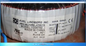
uhmmm the 35-0-35 can go too high after rec/filter = 52V more or less the toroid I have it give me about 53V
I'm not an expert but check resistors sometime I myself misplace them it happens
Regards
Juan
Attachments
hello i have made this AX-11 but output voltage is too high 190milli volts
what to do?
What is this pcb version, there is some mistakes...
hello i have made this AX-11 but output voltage is too high 190milli volts
what to do?
dear sravanth,
ur pcb looks good.from where u get it.how can u measure output voltage.would u like to tell me the procedure to check out put voltage thanks
- Home
- Amplifiers
- Solid State
- 100W Ultimate Fidelity Amplifier