Hi
1) why not use one core w/ bifilar windings?
2) use snubbers on primary switches and more importantly the secondary rectifiers!
3) add common mode chokes on primary for sure and secondary for audio applications.
4) consider other designs for the IRxxxx housekeeping DC supply (see attached from my web search)
5) the more rectifiers you include make sec. grounding isolation better but they also add a lot of HF hash / noise overall.
6) for audio consider using feedback and / or other regulation schemes.
Attachments

Hi !
Thanks for advice !
You mean to solder C5,C11 , HL1 , HL2 from your circuit in series whit gate on mosfet and R3,R4 ?
I think to use EMI filter on primary .
core whit bifilar windings i will change it .... I have this one , but don`t know how much turn to make ....
I use FR302 two at paralell because they are only 3 A . And i have a lot of them .
For output snubers 1n2/400V and 100R/2W ?
In some circuit output core is before rectifiers . Is this a better solution ?
For test it will be without feedback .
well maybe they can provide better support in the DIY thread from which you DL the XFMR design?No , it`s not custom design . I download circuit from this forum . I`t original , i have not change nothing .
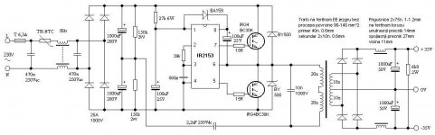
IR2153 + 2xIRF460
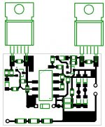
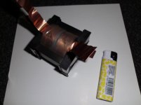
Use this one.
EE33 from PC PSU.
1/2 Primar 20 turns, 0.7mm wire
sekundar 1turn=4V, for example 10turns=40V
and another 20 turns primar.
Use yellow storage inductor from PC on output, 2turn for 1V.
If you need 2x50V connect 2 core with glue, and tthan you need 1turn for 1V.
Don't put 10n/1000V. It works better without it.
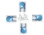
Picture number 6. shows how to disassemble EI33 core in 3 minutes.")
Sorry for my bad English. Regards
Use this one.
EE33 from PC PSU.
1/2 Primar 20 turns, 0.7mm wire
sekundar 1turn=4V, for example 10turns=40V
and another 20 turns primar.
Use yellow storage inductor from PC on output, 2turn for 1V.
If you need 2x50V connect 2 core with glue, and tthan you need 1turn for 1V.
Don't put 10n/1000V. It works better without it.
Picture number 6. shows how to disassemble EI33 core in 3 minutes.
Sorry for my bad English. Regards
Attachments
Last edited:
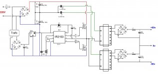
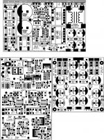
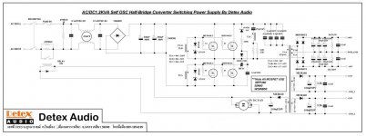
IR2153 with protection
For 50KHz, R1=15K+C1=1nF
100KHz, R1=7K5+C1=1nF
Output Diodes: MUR1660, U1660, MUR860, BYW29, BYV79, BYV42...
For 50KHz, R1=15K+C1=1nF
100KHz, R1=7K5+C1=1nF
Output Diodes: MUR1660, U1660, MUR860, BYW29, BYV79, BYV42...
Attachments
mihailo , thanks for circuit !
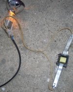
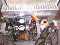
This is the result from first circuit .
Mosfet exploded with sound and light
I not used lamp in series on primary , because on video everything worked.
Now i will try your circuit .
But i have some questions .
1. Why there is no cener dioides on gate . 15 Volt for example
2. Can I use a transformer EI33 without rewind
3. Can I use mosfet for test and if all is OK then replace whit IGBT .
4. Pin 8 cap 100uF/25 in some circuit is 100N .
Which is better electrolytic or ceramic
Regards
1. Why there is no cener dioides on gate . 15 Volt for example
2. Can I use a transformer EI33 without rewind
3. Can I use mosfet for test and if all is OK then replace whit IGBT .
4. Pin 8 cap 100uF/25 in some circuit is 100N .
Which is better electrolytic or ceramic
1.BA159 is not zener diode. It's fast recovery Si-Di <500nS 1000V 1A
You can also use UF4007( NOT 1N4007 ), FR103, FR107, FR154...
Resistors 15R, 27R and diode BA159 very very important for protecting mosfets.
It has something to do with death time, and charging...
2. Yes you can, but then you will get only 2x27V or 2x55V if you use 2 of them.
3. Just use mosfets, no need for replace. Mosfet is better because it can work with more frequency.
IGBT only 30Khz, IRFP460 can work up to 100KHz.
With IRFP460 on 80KHz, and ETD49 or ETD59 transformer, you can get even 1KW power with this basic schematic.
List of compatible mosfets: IRFP450 700-1000W, IFFP460 1-1.5KW. IRF840 200-300W, also 20N60C and some more high voltage mosfets will work.
4. No ceramic. 100uF/25V electrolytic on pin 8.
470nF/275V, 2.2uF/250V, 1nF/63V all POLYESTER (MKT,MKP,MKS,WIMA...), don't use ceramic!
Put on bridge retrifier after 470nF, ceramic 102/1kV, or 472/1KV, or 103/1KV like in this picture:
Also pin1 needs 15V for IR2153 to work. No need for separate transformer, just put 27K/5W or 27K/9W... It will be little hot, but it's ok. 27K/5W provides 15V from 330V.
Output capacitors 1000uF/63V/105'C or 2x470uF/63V in parallel is more than enough for SMPS that works on >50kHz. No need for 4700uF, like in picture. SMPS charges capacitors 100x faster than standard PSU on 50Hz. 4700uF will only make more heat on IRFP460, they probably won't burn because of 30A)) , but some weaker mosfets like IRF840 will explode after some time.
2. Can I use a transformer EI33 without rewind
3. Can I use mosfet for test and if all is OK then replace whit IGBT .
4. Pin 8 cap 100uF/25 in some circuit is 100N .
Which is better electrolytic or ceramic
1.BA159 is not zener diode. It's fast recovery Si-Di <500nS 1000V 1A
You can also use UF4007( NOT 1N4007 ), FR103, FR107, FR154...
Resistors 15R, 27R and diode BA159 very very important for protecting mosfets.
It has something to do with death time, and charging...
2. Yes you can, but then you will get only 2x27V or 2x55V if you use 2 of them.
3. Just use mosfets, no need for replace. Mosfet is better because it can work with more frequency.
IGBT only 30Khz, IRFP460 can work up to 100KHz.
With IRFP460 on 80KHz, and ETD49 or ETD59 transformer, you can get even 1KW power with this basic schematic.
List of compatible mosfets: IRFP450 700-1000W, IFFP460 1-1.5KW. IRF840 200-300W, also 20N60C and some more high voltage mosfets will work.
4. No ceramic. 100uF/25V electrolytic on pin 8.
470nF/275V, 2.2uF/250V, 1nF/63V all POLYESTER (MKT,MKP,MKS,WIMA...), don't use ceramic!
Put on bridge retrifier after 470nF, ceramic 102/1kV, or 472/1KV, or 103/1KV like in this picture:
Also pin1 needs 15V for IR2153 to work. No need for separate transformer, just put 27K/5W or 27K/9W... It will be little hot, but it's ok. 27K/5W provides 15V from 330V.
Output capacitors 1000uF/63V/105'C or 2x470uF/63V in parallel is more than enough for SMPS that works on >50kHz. No need for 4700uF, like in picture. SMPS charges capacitors 100x faster than standard PSU on 50Hz. 4700uF will only make more heat on IRFP460, they probably won't burn because of 30A
)) , but some weaker mosfets like IRF840 will explode after some time.Attachments
Last edited:
List of compatible mosfets: IRFP450 700-1000W, IFFP460 1-1.5KW..
only in someones dreams
after 500W things like switching losses and EMI crash the party.
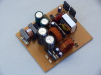
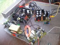
With this schematic on 320DC one pair IRFP460 + IR2153 + ETD59 = 1KW and more.
I had build it, test it, and it works fine for me.
silly to let a $1 controller work for an expensive 1KW design. I guarantee the EMI , switching losses, and the 100Hz ripple will all be horrible. sorry but any decent customer wouldn't touch that rookie thing even with a long stick.
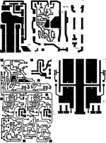
![SMPS-1 [800x600].jpg](/community/data/attachments/371/371386-9d2f26eeca6c5281b60511f3cd88b829.jpg)
- Status
- Not open for further replies.
- Home
- Amplifiers
- Power Supplies
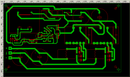
- 220 -> 2x50V whit IR2153 and PCB