Its true that nowadays, the vast majority of PCM recordings are made through an S-D modulator. I rather suspect this fact goes a long way towards accounting for the rather extreme variability of digital recordings in terms of how much dynamics they portray. However it needn't be this way - various vendors have highly capable SAR ADC chips now which boast impressive specs and are reasonably priced. Thinking in particular of both ADI and LT but they're not the only ones, TI and Maxim also make decent-looking parts.
The LT 20 bit ADC looks incredible. I'm sure this would make a damn fine audio
ADC but no marketing dept would wear it being only 20 bits.
The DR looks a bit low - even accounting for a reduced measurement BW.
Maybe you could parallel 2 / 4 / 8 of them and average the result to get more
effective bits.
Z
Yes, the SNR at a relatively measly 104dB looks to be its only weak spot. For 44k1, running at 16X OS it should be possible to get a 12dB improvement on that, to 116dB, non-A weighted. Marketing still might not buy it, but I reckon there might be takers particularly as the chip's only $20 in volume.
It seems to me you're being particularly cryptic tonight Joe
It was just two minutes before going to bed, so no intentions to be other than brief. Now, if you really want me to be cryptic, don't get me started...
BUT... the real problem is with delta-sigma low-bit DACs and their own attendant noise shaping. Today, most PCM of various bits are processed in delta-sigma DACs - unless you use older DACs and NOS-DACs.
Delta-Sigma DACs, what ever source material they use, need a particular form of post-DAC filtering - and I know of no manufacturer who does it and only a couple of DIY'ers that do.
This form of single order filtering has been used for as long as I can remember in many different ways - from straight RC to LC to transformer integrated
filters. The simple RC is the usual first port of call for a simple LPF to see where
the cards lay WRT OOB noise. I and many others have used it for years.
I'm guessing what you mean is it's the first time you have tried it.
think of quite a few ways to implement a decent LPF that -are- linear phase at
the DAC OP without using the usual opamp based circuit.
T
I can think of quite a few ways to implement a decent LPF that -are- linear phase at the DAC OP without using the usual opamp based circuit.
T
Hi Terry, I still think what I am suggesting is not being understood. Definitely not using an opamp, indeed if this was a virtual earth, then a 0.82uF across the current DAC's two phases (not the Sabre DAC) and then two 3R3 resistors to the two Virtual Earths, they then define the impedance for the 0.82uF to get -1.3dB to -1.5dB down relative to 1KHz - and then something happens that cannot be explained by mere frequency response or just filtering. It also works with Burr-Brown DACs, Cirrus Logic also, both "voltage" and "current" and the common denominator is that they are delta-sigma DACs.
At this point, just establishing we are talking about something that is real and not chasing herrings, we need more to just do it and then we can establish there is a need to find out. Or we are just wasting time talking about it.
Cheers, Joe
Last edited:
Hi!
Has anyone tried to use the AD844´s TZ pin´s gain resistor as a form of volumen control ?
It seems to work in my simulation. Maybe noise would be an issue ?
For one thing, DC shifts too much to make it work in practice. Any input offset will change DC on the output as you change gain.
Cheers, Joe
Lowering the resistor on TZ pin will only minimize the output dc offset, so I think you are wrong here....Cheers
Flemming
Joe is saying that any D.C. offset appearing on the TZ pin will be modulated whenever the volume control is changed. This will produce audible low frequency transient noise while the varying D.C. offset charges any output coupling cap. to the new D.C. value.
Joe is saying that any D.C. offset appearing on the TZ pin will be modulated whenever the volume control is changed. This will produce audible low frequency transient noise while the varying D.C. offset charges any output coupling cap. to the new D.C. value.
Perhaps but the offset is very very low, so I dont get your point?
Perhaps but the offset is very very low, so I dont get your point?
Hi Flemming
I suspect it won't be small. But by all means try it. I can assure you, I would have done it in the past when I constructed some microphone preamps (studio use) using 844 and needed variable gain. I could not direct couple as I needed to have multiple gain settings. This chip is very flexible and makes the basis for high quality zero feedback preamp design. But varying Z on both input and TZ changes (or as Ken says, modulates) DC shifts.
Try it, it will be a good exercise for you.
Niels Bohr (who you would have heard of - did you know he lived in that house behind Carlsberg) said: "An expert is a person who has made every mistake there is to made in a narrow field."
No mistakes, no experts.
Cheers, Joe
PS: My older brother's name is Flemming.
And make my own mistakes
I think the moon is still there even if im not looking at it
Lets not mix QM into LF audio
Yes Niels Bohr was a brilliant mind!
Gee I thought it was only in Denmark Flemming was spelled with two m's, and not with only one m, like 007 creator Ian Fleming.
Cheers
Ps.
Carlsberg is a great beer!
:
Gee I thought it was only in Denmark Flemming was spelled with two m's
Where do you think he is?
:
Carlsberg is a great beer!
How about Tuborg?
Cheers, Joe
Where do you think he is?
How about Tuborg?
Cheers, Joe
Hej Joe,
Tuborg is also great
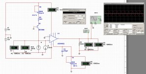
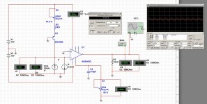
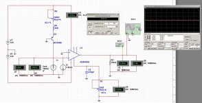
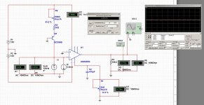
Well today I had a little time to simulate some more on the AD844 and with different values on the TZ load resistor. And I have added some pictures to share below. I the simulation I used the TI PCM1795 as my current generator (+/-2mA FS, -3.5mA Zero offset current). Used a simple common base PNP as current source to null out the -3.5mA. Seems to work well in the simulator.
Then I adjust the emitter resistor of Q1 to trim the current to get near the 3.5mA. but also to null out the DC offset on the buffered Output (pin6).
I configure the AD844 in the Openloop configuration, and I connect a 2K resistor (potmeter R1) to Pin 5 (TZ pin)
Here is a series of simulations, where I half the resistor each time. (eg. Volumen control).
Sim1: R1=2K resistor Frequency for all simulations is 7kHz +/-2mA. Vout = 2.8Vrms, DC offset = 0.82 mV, THD@7kHz = 0.002%
Sim2: R1=1K ohm.
Sim3: R1=500 ohm.
Sim4: R1=250 ohm.
Sim5: R1 = 125 ohm.
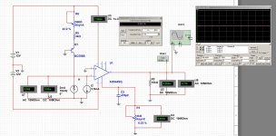
Sim6: R1= 62 ohm.
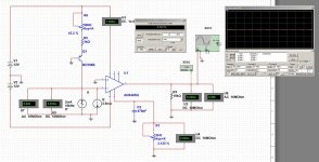
Sim7: R1=31 ohm.
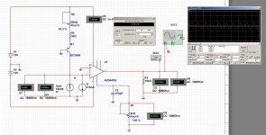
Sim8: R1 = 16 ohm.
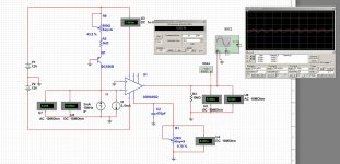
Sim9: R1 = 8 ohm.
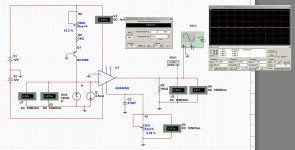
Sim10: R1 = Zero ohm.
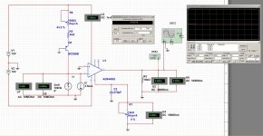
As you can see the DC offset get lower each time it R1 is halved.
Now my question, why would this not work in real life, as mentioned earlier ?
If there is some DC offset on Pin 6, due to temperature drift and what not, an series capacitor is an easy fix I would reckon.
On the other hand, If it works, it is a pretty nice way to implement volume-control on any current DAC
Cheers
Flemming Bach Andreasen
Denmark
There is another big snag, when you vary the TZ resistor your also going to get a different HF roll off because the TZ cap will remain constant, so if you set up for -1db @30khz as I do and then halve the resistor value for less volume without doubling the size cap as well you'll let much more HF crap out to the output buffer and onto the amp/s.
Cheers George
Cheers George
There is another big snag, when you vary the TZ resistor your also going to get a different HF roll off because the TZ cap will remain constant, so if you set up for -1db @30khz as I do and then halve the resistor value for less volume without doubling the size cap as well you'll let much more HF crap out to the output buffer and onto the amp/s.
Cheers George
Here is some -3dB bode plot for very low R1, 500 oh, 1k and 2k ohm.
I don´t think that is a big concern, ? One could and an RC filter after the buffer..
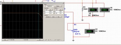
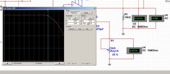
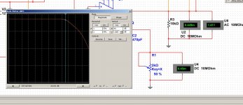
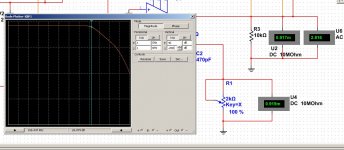
It was to me in practice, as the highs were notably harsh if the rolloff was too high, letting through lots of rubbish.
As for the dc shift with changing of the TZ resistor if it becomes a problem, you could if you devised a dc servo to change slightly null points offset setting on pin 1 and 8 thus changing the 20ohm null pot electronically as the TZ resistor is lowered.
Cheers george
As for the dc shift with changing of the TZ resistor if it becomes a problem, you could if you devised a dc servo to change slightly null points offset setting on pin 1 and 8 thus changing the 20ohm null pot electronically as the TZ resistor is lowered.
Cheers george
- george, was your amplifiers after the AD844 traditional power amp with fair amount of global negative feedback ? This could explain if it started to sound harsh, when to much HF get into the amplifier.
Was your DAC a non OS type ?
I intend to use AD844 as I/V in my ASUS Essence One, 2xPCM1795 in dual mono config (8 x AD844 needed), with oversampling. So the DAC out-of-band noise is pretty low. Volumen control via Pin 5 will not be part of this project.. to much of a nightmare with so many AD844.
For 2-3 years now I have been using passive I/V in the ASUS E1, which sounds very great. (about 180 ohm, 360mVrms from each DAC output) I also has added a singled ended buffered output of this passive converted signal, so I can listen to music that has not been trough any opamps. This is a marvel to listen to!
I also plan to try out AD844 as I/V in my old Kenwood DP-7090 (2x4xPCM1702K multibit DAC)
Have a nice weekend!
Cheers
Flemming
It was to me in practice, as the highs were notably harsh if the rolloff was too high, letting through lots of rubbish.
As for the dc shift with changing of the TZ resistor if it becomes a problem, you could if you devised a dc servo to change slightly null points offset setting on pin 1 and 8 thus changing the 20ohm null pot electronically as the TZ resistor is lowered.
Cheers george
You could couple the Tz pin to the pot through a capacitor, and have a fixed resistor for the Tz DC bias.
How would that work?
At any rate, the issue is exactly the same as any preamp stage with offset needing ac coupling, no?
Jan
You could couple the Tz pin to the pot through a capacitor, and have a fixed resistor for the Tz DC bias.
How would that work?
Need to see specific R values that would work, maybe the cap size would need to be too big?
Maybe just figure out the range of DC shift on the output and put a cap there - in which case, just put the pot on the input, the Tz value fixed, then RC on "+" input and null the DC on the output as the 844 has that facility. If you are going to use a Tz cap, then a cap is a cap and maybe if a cap is needed, then put it on the input.
I know it works because I have done it.
Cheers, Joe
- Home
- Source & Line
- Digital Line Level
- Using the AD844 as an I/V