Single-cycle symmetric (N - P - N channel + P - N - P channel) repeater plated input and cooled with a stable current consumption , regardless of the power consumption of the load . ( Eurasian patent application for an invention 201,300,368 ) Vpit . monoblock +-27V. Quiescent current repeater 2 . 5 A for the N - P - N channel and P - N - P channel in the amount of 5 A. efficiency of about 50 % 0 Hz band , 12 MHz . Each channel 3 pairs of transit . ( Pair this current generator + emiterny repeater) RL - 4th . While CED - 1W 0.012 %. 2.25vt. - 0.015 %. 4W - 0.020 - 0.025 % 6.25vt 9W - 12W - 0.033 % 0.041 % 0.051 % 16W - 20W - 25W - 0.063 % 0.077 % 64 watts. - 0.18 %. With increasing CED pairs decreases. Currents both shoulders supported machine. OR07 applied with a small Vb . Monoblocks are water-cooled completely silent in operation and moreover enough malogabaritny.Pri input closed V noise and ripple Output 0.9 mV R 0.0002 OM .
Attachments
I'm a bit slow to understand.
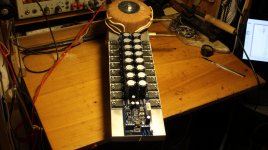
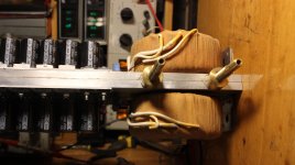
Not sure what the function of the transformer is... not yet.
It's probably obvious?
Also the difference in Z between the load on the top CT of the transformer and the bottom CT is on my mind...
Also not quite clear on how this is thermally stable...other than a servo circuit.
Interesting though.
_-_-
I'm a bit slow to understand.
Not sure what the function of the transformer is... not yet.
It's probably obvious?
...
_-_-
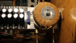
Power transformers...note diodes feeding filter caps to GND.
Just not the way schematics are "normally" drawn...there must be a reason.
")
Got it !
This OP stage runs a combination of class A and B.
1.)When combined at the load neither side is "off".
2.)not as efficient as a typical AB OP , but all devices are not
always on ... a hybrid (efficiency wise).
3.) simulated in isolation (no feedback) ... more stable than a EF3
and the diamond's tempco negates the OPS's nearly perfectly.
CCS's need to be set rather precisely for this to work.
Wild , man! .... (but it works)
OS
This OP stage runs a combination of class A and B.
1.)When combined at the load neither side is "off".
2.)not as efficient as a typical AB OP , but all devices are not
always on ... a hybrid (efficiency wise).
3.) simulated in isolation (no feedback) ... more stable than a EF3
and the diamond's tempco negates the OPS's nearly perfectly.
CCS's need to be set rather precisely for this to work.
Wild , man! .... (but it works
)OS
Attachments
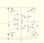
Hi Guys. Now the base currents will not interfere with us. In the scheme of figure 5 and 6 achieved complete isolation of the input currents. A output currents are summed. Repeater efficiency about 50%. Channels are now autonomous. Denominations are indicated on the diagram those used in the pilot sample. A very successful scheme and also a very fine sound.
Attachments
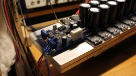
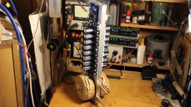
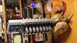
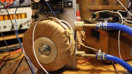
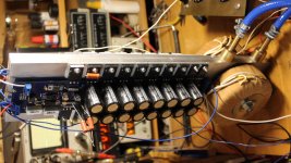
Aqua block assembly. V supply + -30 V, the quiescent current of 6 A. 100 watts in class A. The temperature of 37 degrees of the output transistors, the transistors of the box (not selected according to Kus.) The temperature difference does not exceed 4 degrees.
Attachments
-
 IMG_4838.jpg938.8 KB · Views: 286
 -
 IMG_4839.jpg992.6 KB · Views: 253
 -
 IMG_4840.jpg1,023.8 KB · Views: 207
 -
 IMG_4842.jpg1,005.9 KB · Views: 186
 -
 IMG_4845.jpg977.4 KB · Views: 182
 -
 IMG_4846.jpg947.5 KB · Views: 132
 -
 IMG_4850.jpg897.1 KB · Views: 142
 -
 IMG_4851.jpg1 MB · Views: 138
 -
 IMG_4852.jpg1,009 KB · Views: 142
 -
 IMG_4853.jpg995 KB · Views: 170
Hello FEDOSOFF. Please show the inside of the Aqua block; or its two parts separated. It appears that the screws which mount the power transistors to the block also bring its two parts togethger to seal it. You showed interesting schematics.Aqua block assembly. V supply + -30 V, the quiescent current of 6 A. 100 watts in class A. The temperature of 37 degrees of the output transistors, the transistors of the box (not selected according to Kus.) The temperature difference does not exceed 4 degrees.
Best regards.
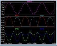
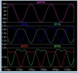
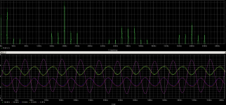
Sir, Akvablok very easy going. If you click on this link Íåîáû÷íàÿ ñèñòåìà Âëàäèìèðà Ïåòðîâè÷à (first laboratory) - Ñòðàíèöà 18, then in this topic to see lots of photos. The main advantage of the scheme - the symmetry, an efficiency of about 50%. Currents in transistors, unchanged, in the amount exactly equal to the load current. Upper picture - Intermodulation, 20k/2k 10/1
Attachments
Thank you FEDESOFF for the llink showing the inside of the block. Fancy; but made [with patience,and accuracy] by using common tools. Consider your schematic on the far left In post#1, I hope that I understand it as follows:
Best regards,
- Has a voltage gain of 1.
- Each unit is a voltage source power amp and a current source power amp operating in parallel. The bjts have their opposed emitters and their opposed collector nodes joined so as to make the power output node.
- Low Zout as a consequence.
Best regards,
Transistor current controlled current device. The output stage has an internal operating system through a current generator, and the control unit synchronously with different signs and controls the current and the current repeater emiternogo current generator. This occurs in each arm but with different signs as transistors of various conductivity. The resulting current flowing (flowing) will always be just that unchanging significant difference determines the absence of many kinds of distortions.DCA control circuit 3-4 SEC. Odnotakty not work for each other, but the load current issue SIMULTANEOUSLY.Initially the current is constant. Now then be continuous in a continuous half-wave then working in a continuous load.
This is exactly parallel to the opening work OK EO ...Recommends that you collect repeater scheme with FET input.Heatsink temperature depends on the power dissipation. Automatic control will maintain a stable current at any temperature radiator. Can be applied to air cooling, but it will dramatically increase the radiator size.
This is exactly parallel to the opening work OK EO ...Recommends that you collect repeater scheme with FET input.Heatsink temperature depends on the power dissipation. Automatic control will maintain a stable current at any temperature radiator. Can be applied to air cooling, but it will dramatically increase the radiator size.
Attachments

Thank you FEDOSOFF for your explanation, and the picture of the insides of the cooling block. I am a chemist, and always try to educate myself in audio electronics with novel schematics and designs. I thought more about a potential bias regulator if needed and/or for peace of mind to augment the inherent stability of the amp. It comes down to managing the base currents to the power output bjts. This requires that a thermally sensitive element be put in both constant current circuits of the front end. I'll post a simple concept schematic to explain it for the benefit of other DIYers.Transistor current controlled current device. The output stage has an internal operating system through a current generator, and the control unit synchronously with different signs and controls the current and the current repeater emiternogo current generator. This occurs in each arm but with different signs as transistors of various conductivity. The resulting current flowing (flowing) will always be just that unchanging significant difference determines the absence of many kinds of distortions.DCA control circuit 3-4 SEC. Odnotakty not work for each other, but the load current issue SIMULTANEOUSLY.Initially the current is constant. Now then be continuous in a continuous half-wave then working in a continuous load.
This is exactly parallel to the opening work OK EO ...Recommends that you collect repeater scheme with FET input.Heatsink temperature depends on the power dissipation. Automatic control will maintain a stable current at any temperature radiator. Can be applied to air cooling, but it will dramatically increase the radiator size.
Best regards.
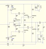
Hello FEDOSOFF. Please find attached a picture of a potential bias regulator for the amp schematic you showed in post #1 [far left]. I only show this circuit for the +E rail only. I drew a classical bias regulator [normally used for a generic class AB amp as an example] in the base circuit of the constant current source generator in your schematic. Its Io will vary inversely with the temperature of a classical heatsink.Thank you FEDOSOFF for your explanation, and the picture of the insides of the cooling block. I am a chemist, and always try to educate myself in audio electronics with novel schematics and designs. I thought more about a potential bias regulator if needed and/or for peace of mind to augment the inherent stability of the amp. It comes down to managing the base currents to the power output bjts. This requires that a thermally sensitive element be put in both constant current circuits of the front end. I'll post a simple concept schematic to explain it for the benefit of other DIYers.
Best regards.
Best regards.
Attachments
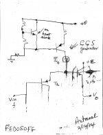
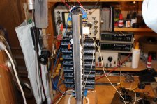
Figure 13 is a valid model sample . To adjust the current Chinese reguriruemye applied voltage sources . As a current meter apply any suitable voltmeters . Power supply + and - 27volt . Current balance is selected by changing the voltage on the twelve volt sources pitaniya.V load out almost the entire total current . While arrows Ammeter immobility. ! A very low intermodulation distortion above this range . Signal is input from an external DAC PSM1794A direct conversion (PSM1794 simultaneously performs the function of the amplifier output V plated ) . PSM1794A also serves as a voltage amplifier - About SB - 20 V Breaks .
Attachments
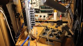
Моя система ретранслятора 120 Вт Класс - три полосы идеально AKVABLOK решение ?????????? ???????????? ??????????? - YouTube и даже каток ?????????? ???????????? ???????????. ????? 2 - YouTube http://youtu.be/JK9jl-sgFgU здесь видео
Last edited:
I was absolutely amazed at your lab, your delicate woodwork of the various cabinets, your practical invention, and the ease with which you described it. Although your cat knows way more more Russian than I do, I came to believe that you are a first rate and gifted scientist. Your video is a must see by DIYers.Моя система ретранслятора 120 Вт Класс - три полосы идеально AKVABLOK решение ?????????? ???????????? ??????????? - YouTube и даже каток ?????????? ???????????? ???????????. ????? 2 - YouTube ??????????? ???????????? ??????????? - YouTube здесь видео
Best regards
The circulation is not used. Cooled by running water from the tap. Small stream. Due to the flow maintain a stable temperature. To protect postavte thermoswitch 60 - 70 degrees. Switch the power cord included in the transformer.Nice video. Do you use a separate cooling tower/condenser?
- Status
- This old topic is closed. If you want to reopen this topic, contact a moderator using the "Report Post" button.
- Home
- Amplifiers
- Solid State
- Single-cycle symmetric (N - P - N channel + P - N - P channel) repeater plated input