Hi tubes world!
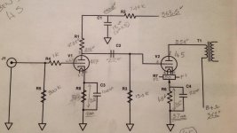
I have a chance to work on a friends 45 amp. He wanted to see if I can rebuild it for him, so I took some measurement to see what I have to begin with. Anyway, I've also been trying to learn how to plot load line and when I try to plot a load line for the 417a I notice that it's not where I think it should be. The plate voltage seem high and the B+ seem high also, if I'm right the load line seem to be way down on the bottom of the curves so gain and linearity are not good.
So, please help me learn how to figure this out.
My plan is to load the 417 with a CCS set at 25ma, -1.5v on the grid B+ @ 220 and plate voltage of 140.
With these numbers I try to do some math and I got gain of 40 and plate dissipation of 3.4 watts.
If someone can plot these two plots for me so I can confirm if I got this right.
Thanks!
Attachments
There is more to it than that, you want to consider tube life and also determine what is best for linearity over the intended operating range. If you have LTSpice (you can download it for free from Linear Tech) you can approximately optimize performance using a circuit model before you build. See the tube models sticky here for more details.
My plan is to load the 417 with a CCS set at 25ma, -1.5v on the grid B+ @ 220 and plate voltage of 140.
With these numbers I try to do some math and I got gain of 40 and plate dissipation of 3.4 watts.
If someone can plot these two plots for me so I can confirm if I got this right.
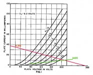
Your numbers are correct. But 25mA is indeed pretty hot for a valve rated only for 40mA.
As I was saying, I am trying to learn how to plot ( understand ) plate's curves.
I though you need to calculate for linearity by aiming for the straighten part of the curves where it is spaced out evenly and as long as I don't go over the dissipation limit.
Can you guys elaborate more on how to plot these curves for the 5842/417a for this amp?
As for the measurement according to the schematic I posted, the 417a is @10ma but when I try to draw a load line using the measurement I have it's seem that the b+ and plate voltage seem high. As for gain. How much gain do I need to consider for this design?
I was thinking of using 5687 instead but didn't think there is enough gain by itself.
As for the measurement according to the schematic I posted, the 417a is @10ma but when I try to draw a load line using the measurement I have it's seem that the b+ and plate voltage seem high.
Your measurements and the loadline look pretty spot on to me... The supply voltage is indeed beyond the maximum rating given on the data sheet, although the data sheet figure (200V) is suspiciously low.
http://www.westernelectric.com/spec_sheets/417A.pdf
Your output tube is biased to 56V, so for maximum swing you need 112Vpp. Probably less in reality, as the output tube probably isn't biased dead-centre. Call it 100Vpp, or 35Vrms. If you want the amp's sensitivity to be 1Vrms then you need a gain of 35. I think you have about 40 at the moment, which is also fine (a bit more sensitive).As for gain. How much gain do I need to consider for this design?
Attachments
Last edited:
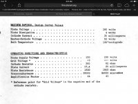
While the 45 is not an overly difficult tube to drive, with the current supply voltage, I would recommend increasing the cathode bias resistor to 1.74K. This will get the static current around 34ma which is much better for the 45 and plate dissipation will be at 10 watts (just at spec). The cathode/plate voltage will be pushing 300V (right around spec). I run my 45 SET amps with this biasing and they are very clean and will push 2.25-watts before clipping (I also use a grid resistor value of 249K and a 0.22uF coupling cap).
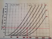
Having said that, your driver requirements still are not trivial. Voltage swing at a minimum is 120 volts peak-to-peak (and you can easily use all of it). Adding a 25% margin to ensure linearity at the driver puts the requirement at 150 volts peak-to-peak. Divide this by the actual in-circuit gain of the driver (likely to be closer to 35) and the input signal at the 417a grid is ~4.3 volts peak-to-peak. Do the math here with some margin and you'll want around -2.75 volts of grid bias. Also look at the plate loading to ensure you can get 150 volts of swing while keeping it in a linear region.
Regards, KM
5842/417a is rated at 4 watts the heater does about 1.89 watts for longest life try to stay close to the heater output or less . Well at least that has worked well for me the last 35 years.
so, what you're saying is to consider the heater dissipation when calculating plate's dissipation? so.. if 2.11 plate +1.89 = 4 watts.
sorry I don't really get it.
Reading this article and understanding the sidebar math will also be useful:
http://www.wavelengthaudio.com/bugle.pdf
Regards, KM
http://www.wavelengthaudio.com/bugle.pdf
Regards, KM
No what I do is keep the plate dissipation equal to or less than the heater it produces a long life from the tube. Thus plate at 1.89 or less.so, what you're saying is to consider the heater dissipation when calculating plate's dissipation? so.. if 2.11 plate +1.89 = 4 watts.
sorry I don't really get it.
No what I do is keep the plate dissipation equal to or less than the heater it produces a long life from the tube. Thus plate at 1.89 or less.
This is completely arbitrary and misleading advice. Heater power is independent of anode dissipation. Yes, it is a general truth that more anode dissipation will lead to more outgassing, and higher anode current will lead to faster cathode evaporation. In other words, the harder you work the valve, the sooner it wears out (obvious really). But plucking a number like heater power out of the air, and trying to connect it with anode power, will only confuse beginners.
Tim, run the tube as hard as you like. It's your tube, after all.
This is not plucking a number out of the air it is 35 years of using tubes and the RCA red book . I gave a point to experiment from . Where does the energy come to drive the electron flow from Cathode to plate ? The heaters . Thus by using that point of reference as RCA did back in the 30s a beginner will be safe to operate the tube in a range that will work for an extended period. Bendix Tung-sol, Mullard and Genelex also have much the same reference for long life.This is completely arbitrary and misleading advice. Heater power is independent of anode dissipation. Yes, it is a general truth that more anode dissipation will lead to more outgassing, and higher anode current will lead to faster cathode evaporation. In other words, the harder you work the valve, the sooner it wears out (obvious really). But plucking a number like heater power out of the air, and trying to connect it with anode power, will only confuse beginners.
Tim, run the tube as hard as you like. It's your tube, after all.
This is completely arbitrary and misleading advice. Heater power is independent of anode dissipation. Yes, it is a general truth that more anode dissipation will lead to more outgassing, and higher anode current will lead to faster cathode evaporation. In other words, the harder you work the valve, the sooner it wears out (obvious really). But plucking a number like heater power out of the air, and trying to connect it with anode power, will only confuse beginners.
Tim, run the tube as hard as you like. It's your tube, after all.
thanks merlin,.
its not my amp. its my bud, and im trying to understand the circuits. its just that I wanted to learn from this project, the plates curves and how to pick the operation point is what really new to me. ive been trying to study more on this subject and I am, still very fresh on this.
I am planning to load the 417 with a ccs and work with the plate curves to pick the best operation point. if I can get you guys to plot this for me It would be nice, and I can see how its done and why. this is how I can learn the quickest.
I just got a book ( John F Rider ) Inside the vacuum tube to learn the basic of load line and such, it will take some time to digest all of this but I will get it sooner or later.
CCS has very high impedance, so just pick your Ea and Ia and put a horizontal line through it. The red line is the CCS load line, the blue line is the capacitor coupled AC load line in the following example:
An externally hosted image should be here but it was not working when we last tested it.
- Status
- This old topic is closed. If you want to reopen this topic, contact a moderator using the "Report Post" button.
- Home
- Amplifiers
- Tubes / Valves
- 417a load line