Use the sqrt(2) factor. IT IS ACCURATE.
Then make allowance for diode Vdrops and resistive Vdrops and ripple voltage and the used portion of transformer regulation.
When you do this, the prediction using your PSU model is far more accurate than guessing at 1.3 for a factor.
but hopeless for a beginner to to calculate while searching for a transformer.
and accuracy is not that important. if one end at 50VDC or 53VDC dos not matter.
and the accuracy goes straiht out the window anyway when the rest of the neighborhood comes home and turn on their stows and washing machines
")
I'm searching a couple of soft start modules, what do you think about these?
Power Soft Start v3
or
Power Soft Start v4
I have another question.. which preamp (gain?!) is suggested for the F5T amp?
those looks fine.
preamp is all about taste. you don't need much gain from it when you have 22db gain in the F5.
J-fet boz, is simple as hell. and People like the sound (have not tried it yet)
aleph P1.7. more complex and expensive. but i love it with the F5.
B1. but this is a buffer whitout gain.
the *1.414 is useless in a class A amp. there will be more like VAC*1.3. ...............
Make up your mind..............and accuracy is not that important. if one end at 50VDC or 53VDC dos not matter........
does the difference between *1.414 and *1.3 matter? <8.8%
Or is it unimportant?
How hot do I go?
Hey guys,
I slept on it last night and I can see upcoming issues...
It is obvious from your statements that I must get some sort of readings for how I can dissipate heat. What means might I use to take and report a reading? Is there a standard way to apply and measure resultant heat?
I can double up on heat sinking more easily than any other aspect of this build In fact I'd be silly Not to double up on heat sinking, maybe 100 pounds worth
I have twin 1000VA transformers designed to make 60VDC. You can see where I am headed with this?
I know using very high rails causes issues with the FE boards and the FETs. (I could build a separate power supply for the front end...) Am I crazy to even think of using those transformers and 60V rails?
Hey guys,
I slept on it last night and I can see upcoming issues...
It is obvious from your statements that I must get some sort of readings for how I can dissipate heat. What means might I use to take and report a reading? Is there a standard way to apply and measure resultant heat?
I can double up on heat sinking more easily than any other aspect of this build
In fact I'd be silly Not to double up on heat sinking, maybe 100 pounds worth I have twin 1000VA transformers designed to make 60VDC. You can see where I am headed with this?
I know using very high rails causes issues with the FE boards and the FETs. (I could build a separate power supply for the front end...) Am I crazy to even think of using those transformers and 60V rails?
Make up your mind.
does the difference between *1.414 and *1.3 matter? <8.8%
Or is it unimportant?
the point being. you will NEVER get enything near the *1.414 numbers with class A. regardless of conditions.
IMHO, you'll learn more figuring out the losses to account for starting with 1.414. Download PSU designer, model your transformer properly, then insert your proposed power supply and you can see the expected voltage drop.
Remember that the transformer manufacturers usually rate the secondary voltage at rated load, so in the usual grossly over-specified transformer, the in service secondary voltage is likely to be a bit higher than nominal. This can be modeled in PSU designer. Take a look at Antek's 35V 500VA transformer as an example. At the expected 240W dissipation will likely be an extra volt after rectification before you start losing in the CRC. From Antek's website:
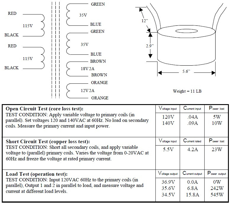
Remember that the transformer manufacturers usually rate the secondary voltage at rated load, so in the usual grossly over-specified transformer, the in service secondary voltage is likely to be a bit higher than nominal. This can be modeled in PSU designer. Take a look at Antek's 35V 500VA transformer as an example. At the expected 240W dissipation will likely be an extra volt after rectification before you start losing in the CRC. From Antek's website:
Hey guys,
I slept on it last night and I can see upcoming issues...
It is obvious from your statements that I must get some sort of readings for how I can dissipate heat. What means might I use to take and report a reading? Is there a standard way to apply and measure resultant heat?
I can double up on heat sinking more easily than any other aspect of this build
I have twin 1000VA transformers designed to make 60VDC. You can see where I am headed with this?
I know using very high rails causes issues with the FE boards and the FETs. (I could build a separate power supply for the front end...) Am I crazy to even think of using those transformers and 60V rails?
i bet this transformer is 2*40VAC. wich will give you about +/-52VDC.
and now. the voltage is no problem. cascode the input fets and your good. and make sure your caps can take the voltage.
hot rails v3
It is clear to me that both calculation and a build is necessary to know what the rails will turn out to be. For my part in suggesting the possible 60V rails for my v3, I know this to have been the resultant voltage with these exact transformers though with a different smothering (pi) filter so I'd guess there could be a volt or two difference...which I can and will explore!

It is clear to me that both calculation and a build is necessary to know what the rails will turn out to be. For my part in suggesting the possible 60V rails for my v3, I know this to have been the resultant voltage with these exact transformers though with a different smothering (pi) filter so I'd guess there could be a volt or two difference...which I can and will explore!
jdg,
At 36W per device (60V x .6A for non FAB) you're pushing it, no matter what the heat sink capacity. It's doable, but every thermal interface must be near perfect. Use Keratherm and lap the sinks to your spreader carefully then use a thin smear of grease.
High rails alone won't get you any more class A power. For that you need more bias, and since you are already maxed out per device the solution is more output devices. (which is also the solution if you want to reduce per device dissipation) You are entering into dual input jfet territory if you want to maintain the bandwidth. Quite a project.
Could your transformers be better suited for class AB amps for your subwoofers and buy new for your F5 (like the Crowns they came from)?
could that be 40Vac + 5% regulation?I believe the transformers are 42V secondary. I have to check. They come from Crown DC300A amps...
IMHO, you'll learn more figuring out the losses to account for starting with 1.414. Download PSU designer, model your transformer properly, then insert your proposed power supply and you can see the expected voltage drop.
Remember that the transformer manufacturers usually rate the secondary voltage at rated load, so in the usual grossly over-specified transformer, the in service secondary voltage is likely to be a bit higher than nominal. This can be modeled in PSU designer. Take a look at Antek's 35V 500VA transformer as an example. At the expected 240W dissipation will likely be an extra volt after rectification before you start losing in the CRC. From Antek's website:
f.ex with transformers from Antek(that is tested with 120V mains) , most that have 230V mains acctualy HAVE 230V mains. and then they need to shave off 5% of the sec voltage that Antek states
f.ex this 500VA 2*35V would acctualy give 2*35V with NO load.The 128Vac will give you a lower output voltage.
It will also run the transformer at lower flux and as a result slightly cooler and slightly less noisy.
Connect it up using the high primary tapping and measure the open circuit output voltage and carefully measure the primary voltage.
It will also run the transformer at lower flux and as a result slightly cooler and slightly less noisy.
Connect it up using the high primary tapping and measure the open circuit output voltage and carefully measure the primary voltage.
I got +-58.5Vdc from a 230:40,40Vac transformer, when bias was set to ~500mA and mains was at 240Vac.
I suspect somewhere approaching 43,43 would get to your target +-60Vdc.
Is that what you have?
remember that your mains are 5% higher then the 230V(wich most have) test to get 40V sec.
and 500mA is not near a 2.5A bias.
- Home
- Amplifiers
- Pass Labs
- F5 Turbo Builders Thread