Coris, what is your I-V arrangement?
From memory you stated you were using differential opamp, ie; virtual
ground? If this is the case the caps across DAC OP's work in a completely
different way and yes you do increase noise gain, distortion etc.
You also change the compensation. There is a correct way to do this and
I believe a few white papers written on it.
T
I use OPA1632 on DAC outputs, with feedback as usually, and then the final opamp, without any filtering in between. This set up gave me the best sound so far, even though the DAC residual HF noise.
My useful audio signal goes up in a range of 16Vpp at the DAC system output (3x gain). The residual HF noises reach few hundred mVpp (in the same point). The noise it may be even reduced to few teens mVpp at on the RCA outputs (by other means than using caps or coils).
Using the filtering cap over the phases, it modify the HF noise shape or even the level, as the capacity of this cap increase. As Joe have also observed, there is a critical capacity value, over this HF noise and the functionality of the system get very worse, with many negative side effects over the useful signal.
Using this cap inside the critical zone, even though a slightly increasing of the HF noises, there is evident in the same time the improvements for the useful audio signal. Actually, there is not exactly the audio signal improved, but the perceptual sound stage, which this audio (stereo) signal it realize.
There is obviously (actually in my opinion...) that using this filtering method one gets improvements in perceptual sound stage. I do not know exactly what the reasons of this are, but I suppose it is happen something with the phase’s differences/changes in the components of the audio signal outputted over the two stereo channels. There it may be a more precise reproduction/transmission/fidelity in this area, which leads to a much better localization of the sounds inside a sound stage. This is to be observed using enough good recordings…
The sound stage become larger, so that one can identify a lateral sound source almost 180 deg. in the front of the listener. The sounds do not come out longer directly from the speakers, but are perceptual created in space in front of the listener. One can clearly identify the cymbals position when are hit it by the drummer in a band, the same for the many drums around. One can identify the sources positions of a dual vocal "set up", or the instruments in background of the voices in a band. The bass become very penetrating (in a very positive way), well defined by the stereo sources, and its vibrations are well felt, not only heard... The audio image is huge and with a very good resolution.
All things it happen with a moderate to low signal volume level and/or power from the amplifier. I run my amp with no more than 10W in a moderate large room.
I really think that something like this it may not be possible if the important noise over signal or high distortions levels will occur in the system...
")
As Joe has previous demonstrate, to apply this filtering method is not difficult at all and is fully reversible. No any danger at all. A little bit work is necessary to find the right capacity value (one should use SMD components) for the ones particular set up. One may very well start with a quite low capacity values...
Why not just solder such caps on your gear and hear the difference. Then come here with (negative) comments…
Last edited:
As Joe have also observed, there is a critical capacity value, over this HF noise and the functionality of the system get very worse, with many negative side effects over the useful signal.
...but the perceptual sound stage, which this audio (stereo) signal it realize.
There is obviously (actually in my opinion...) that using this filtering method one gets improvements in perceptual sound stage. I do not know exactly what the reasons of this are, but I suppose it is happen something with the phase’s differences/changes in the components of the audio signal outputted over the two stereo channels. There it may be a more precise reproduction/transmission/fidelity in this area, which leads to a much better localization of the sounds inside a sound stage. This is to be observed using enough good recordings…
The sound stage become larger... The sounds do not come out longer directly from the speakers, but are perceptual created in space in front of the listener...One can identify the sources positions of a dual vocal "set up", or the instruments in background of the voices in a band. The bass become very penetrating (in a very positive way), well defined by the stereo sources, and its vibrations are well felt, not only heard... The audio image is huge and with a very good resolution.
I really think that something like this it may not be possible if the important noise over signal or high distortions levels will occur in the system...
As Joe has previous demonstrate, to apply this filtering method is not difficult at all and is fully reversible...
Hi Coris
I fully anticipated your description in every detail. In fact, what is done, if you can't hear it, you must have cloth hearing and clearly you don't.
This technique seems to be particularly needed for delta-sigma DACs, true multi-bit DACs don't need it and in fact, this now starts to sound closer to that NOS-DAC sound that some absolutely hanker for. That is a tonal solidity and natural expansiveness, especially in the midrange - but there are plenty of benefits other than that.
I decided not to keep this to myself - just seems there is a need for this just get out there - and then also may lead, not just to better sound, but also a better understanding of what is happening on a more technical level.
To me this is a noise issue, that I have no doubt about, so it is the noise-shaping that has to be at the centre of it, IMO.
Cheers, Joe
3M absorbing materials and WA Quantum
Ric and others,
I wonder if these 3M AB5000 Series series RFI absorbing materials are an explanation for the WA Quantum capacitor and DAC chips?
They are about the same size and shape and could explain the beneficial properties (assuming that they exist, I have never used these WA chips myself). Placing an RF absorber on top of a DAC chip, or potentially on top of an output coupling capacitor might reduce high-frequency noise. By the way, these are available from digikey in stock for about $10-$20 for an 8 inch by 11 inch sheet, or also in narrow tape format. This would provide a lot of small dots…
Ric have you measured the performance of your WA chips? In particular one could look at whether the 100 MHz band noise is being attenuated out of the output coupling capacitors. Or one could look at RF radiation from the DAC chip. Of course, the 3M materials are well characterized and inexpensive options for these issues.
Eric
Hi Coris
I fully anticipated your description in every detail. In fact, what is done, if you can't hear it, you must have cloth hearing and clearly you don't.
This technique seems to be particularly needed for delta-sigma DACs, true multi-bit DACs don't need it and in fact, this now starts to sound closer to that NOS-DAC sound that some absolutely hanker for. That is a tonal solidity and natural expansiveness, especially in the midrange - but there are plenty of benefits other than that.
I decided not to keep this to myself - just seems there is a need for this just get out there - and then also may lead, not just to better sound, but also a better understanding of what is happening on a more technical level.
To me this is a noise issue, that I have no doubt about, so it is the noise-shaping that has to be at the centre of it, IMO.
Cheers, Joe
It may be quite interesting that the HF noises it may improve in this case the audio signal out of a DAC... I do not know, I`m not very sure about... Maybe.
Anyway there is an obvious improvement using these caps in that place. One may note here that it were reported about improvements in cases when it were used two different configurations and/or DAC chips. I really think that this is quite important...
I`m a little bit disappointed that are only me and you who has experienced, have commented and try it this trick. It could be nothing easier than put these caps in place on a DAC... and listen the results.
It could be nice to have a larger discussion about this case, trying to find out more, with many involved people who may try it, and commented their results. But nothing of such so far...
Last edited:
Ric and others,
I wonder if these 3M AB5000 Series series RFI absorbing materials are an explanation for the WA Quantum capacitor and DAC chips?
...............................................................
Eric
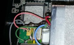
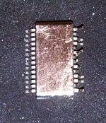
There is beneficial and in my opinion, the DAC chip, as some other components of a DAC system it have to be shielded...
One may use expensive or cheaper materials (as a copper foil), but one may shield these components in one way...
These it may be examples of chip shielding (with grounding)...
In one picture is shown a way to shield an already soldered chip. The another picture it shows (a better) shielding of a chip which is going to be (custom) soldered... The second way of shielding it is not at all a production way to do it...
In one picture is shown a way to shield an already soldered chip. The another picture it shows (a better) shielding of a chip which is going to be (custom) soldered... The second way of shielding it is not at all a production way to do it...
Attachments
Last edited:
...Once determined and we get a consensus opinion, then maybe we could discuss what is really going on. The audible effect is similar to applying 'damping' to circuits that needs damping. Rolling off the top end and it doesn't get slower sounding, but actually faster sounding....Cheers, Joe
Joe,
My initial thought on this is that the filter cap. is providing a small degree of additional 'windowing' to the SINC function sharp transition-band of the digital interpolation filter. Similar to what happens with the 'slow roll-off' DF setting of many DAC chip integrated filters, only not as pronounced. For example, in the PCM179x family, this DF setting gives about -2.5db @ 20KHz.
Perhaps, -1.3dB @ 20KHz is a sweet spot of sorts, providing just enough of an transition-band easement of the DF brickwall cut-off to give an audible improvement in time-domain related effects (i.e., Gibbs phenomena reduction) without obvious harm to the perceived treble balance. Filter more than -1.3dB @ 20KHz and, perhaps, the treble balance is then audibly impacted.
Last edited:
In this case, it seems that a pair of standard RC filter to ground In this location might work better, and should have improved high-frequency rolloff characteristics.
One of the things that concerns me about the current scheme is that these outputs are being connected not to ground, but to another noisy point in the circuit. Coris has said that high-frequency noise is not being attenuated by this current scheme.
I am also concerned about the high levels of distortion that he observed on his oscilloscope.
Eric
Trying to prevent some confusions, I think to precise once more, that when about increased noise (using this cap trick), there is about HF noises. I mean the residual noises due to the digital processing inside the DAC chip. These kind of noises are not to be heard... but it may have negative impact for audio signal in some circumstances.
My preliminary measurements it were made on a 1792 DAC chip. This chip generate a quite high level of HF noises as normal, for the given audio signal it output. Once one add a cap in between the DAC output phases (or I/V input), the DAC`s HF noises increases as the cap`s capacity value increase. There is about a quite low (moderate) HF noises increasing, until a so called critical cap value is reached. Increasing further the value of the cap over the phases, leads to a quite dramatic and suddenly increasing of the HF frequencies. A obvious degrading of the useful audio signal outputted is to be observed over that cap critical value. The audio signal is full of HF noises over on it, but the test signals are not distorted. If is scoped with HF bandwidth limiting is shows well, but degrading is obvious by listening the result.
What is very special in this way of using caps over the phases, is that until one reach the critical cap value, the improvement of the audio signal is a fact. Huge improvements is to be observed in sound scene as in reproduction of the low end audio frequencies. The "power" of the audio signal increase (for the same gain or amplified used volume level), as the dynamics are much improved. Over a certain capacity of the cap used, all the outputted signal is strongly degraded.
In all this experiment is not to be observed (heard) distortions of the audio signal. The signal is not distorted (over the critical cap value). There is very clear an well defined sound to be heard. The degrading is in sound scene, as the high end of the audio spectre is strongly dumped (attenuated), the bass become very dominant. But no any distortion.
Again, one may not only read here about my and Joe`s opinions, in this case. While is very easy and without any damage, to solder in some small caps over the phases of the own`s gear, one may have own impressions, conclusions, remarks, about this. Shearing here the another's own opinion based on one`s own experimenting, it may be beneficial for all of us, to understand better what is going on with this way of filtering.
I may for sure be not the only one who could scope in this case... I personally intend to go deeper in the case, after I will implement it on a Sabre DAC. But in between, somebody else can try it, hear the result and do some measurements...
At least two or only few people (until now) have experimented so, on two different DAC types, have found out almost the same behaviours of the circuits, and have recognized what another one have described as results or procedure to be done. Is not this enough interesting?
This trick works and the positive results are obvious. Just try it by your self (DIY)!
As Joe it were so kind to share this trick here, another one will may be also kind and useful to came here and share his own conclusions (based on facts, real experimenting, measurements), for a constructive further discussion.
Last edited:
Trying to prevent some confusions... This chip generate a quite high level of HF noises as normal.. Once one add a cap in between the DAC output phases (or I/V input), the DAC`s HF noises increases as the cap`s capacity value increase. There is about a quite low (moderate) HF noises increasing, until a so called critical cap value is reached...
What both Coris and I are saying, to low a value cap and it gets worse, but at a certain point, increasing the cap value and suddenly, rather than getting even worse, it turns around and gets better. It is not intuitive and hence confusing.
But it is worth it - and for everybody I have done it, the improvement is very obvious and its works and is a big plus when it comes to musicality - it simply sounds more natural and with lots of other benefits.
Guys, this is DIY Audio... do your thing.
This is why we have an advantage over conservatively minded (and short-sighted) manufacturers.
We are the true explorers!
Cheers, Joe
Joe,
My initial thought on this is that the filter cap. is providing a small degree of additional 'windowing'... this DF setting gives about -2.5db @ 20KHz.
Perhaps, -1.3dB @ 20KHz is a sweet spot of sorts, providing just enough of an transition-band easement of the DF brickwall cut-off to give an audible improvement in time-domain related effects...
Thanks Ken, this is definitely a discussion that is to be had - rather than just dismiss it out of hand. What we are hearing is very real and there has to be a rational explanation for it.
It also seems to be a definite delta-sigma (hence noise IMO) DAC thing. I am basically an analogue guy, but I do hear what you are saying and I have a thought:
My understanding from Coris' postings, if I have got it right, then he has actual noise measurements derived from using different cap values.
To Coris, is it possible to post those measurements in graph form?
Then we could invite comment on them - and show there is something factual happening and those with a knowing eye may spot what is going on.
Cheers, Joe
Hi, Joe,
I have my doubts about this effect stemming from the 1st order filtering of the ultrasonic noise of sigma-delta operation. I feel this way because the effect indeed comes on surprisingly abruptly. It practically switches on and off, with a seemingly minor change in the value of the filter cap. For example, in my own PCM1794A based DAC, which utilizes 75 ohm passive I/V resistors, 4.7nF produces no audible affect. However, when I increase the value to 6.8nF the effect switches on. I can't see how this could be due to the difference in filter response between the two values, but perhaps it is in someway.
I have my doubts about this effect stemming from the 1st order filtering of the ultrasonic noise of sigma-delta operation. I feel this way because the effect indeed comes on surprisingly abruptly. It practically switches on and off, with a seemingly minor change in the value of the filter cap. For example, in my own PCM1794A based DAC, which utilizes 75 ohm passive I/V resistors, 4.7nF produces no audible affect. However, when I increase the value to 6.8nF the effect switches on. I can't see how this could be due to the difference in filter response between the two values, but perhaps it is in someway.
For example, in my own PCM1794A based DAC, which utilizes 75 ohm passive I/V resistors, 4.7nF produces no audible affect. However, when I increase the value to 6.8nF the effect switches on...
Hi Ken
I assume then you heard the effect?
Cheers, Joe
Hi Ken
I assume then you heard the effect?
Cheers, Joe
Yes, I do. The effect is not subtle. Not only does the sound become smoother, it simultaneously becomes more detailed, plus the soundstage becomes larger and more three dimensional. The effect is similar to what I hear via the 'slow' roll-off setting of the PCM1794A's digital filter, except it shows greater subjective focus, along with superior rejection of the undesired ultrasonic alias images than is obtained via the 'slow' filter setting. It's quite interesting to be able to make the sound go from 'digital edginess' to 'analog smoothness' via such a seemingly small change in a 1st order output filter.
Ken - what calculations are you using for your low pass filter?
Is the filter in parallel with the i/v resistor, ie, piggybacked?
Tom,
I determined the value for my system empirically, by ear. The best result with the 75 ohm I/V resistors of my DAC (and using a standard value capacitor), was 6.8nF. While I haven't measured the frequency response, my calculations predict that the response is -0.5dB @ 20KHz. This seems to be right on the fine edge of 'activating' effect, at least to my ears, and isn't' far from the -1.3dB minimum figure that Joe recommends. For example, I do not hear the effect when using 4.7nF, even though the frequency response difference is less than 0.2dB! I know, I know, but that's what I hear.
In my DAC, I use only one phase of the PCM1794A's differential outputs, grounding the opposite phase output. The 75 ohm I/V resistor is connected to ground through the active phase output pin, with the 6.8nF cap. placed in parallel (yes, piggybacked). I observed that as I increased the cap. value above 6.8nF (up to 15nF) the effect remained, yet became increasingly diffuse or less focused. Eventually becoming overtly soft sounding in way that live music is not. By the way, the caps. I used were Wima FKP-2 film-and-foil units.
If you tell me the DAC chip, and the input resistance of your I/V circuit, I will suggest a range of cap. values for you to experiment with. Keep in mind, and as Joe observed, the effect comes in quite abruptly, so I suggest that you begin by listening with the smallest value cap. in the range and moving to the next largest standard value, listening in between, until you hear the effect come in. Which I find to be rather obvious when it occurs.
Last edited:
If you tell me the DAC chip, and the input resistance of your I/V circuit, I will suggest a range of cap. values for you to experiment with. Keep in mind, and as Joe observed, the effect comes in quite abruptly, so I suggest that you begin by listening with the smallest value cap. in the range and moving to the next largest standard value, listening in between, until you hear the effect come in. Which I find to be rather obvious when it occurs.
Thanks Ken - I'm using an AD1865. Two chips in fact, in balanced configuration with 75R resistors, which then goes to a preamp which drives the power amp.
I also have an unbalanced AD1865 with a single chip, using 330R (like your AD1865) resistors here, directly driving a power amp.
As an aside, and not to drag the thread too far off topic, what are the noticeable sonic differences between the AD1865 and the PCM1794?
Thanks Ken - I'm using an AD1865. Two chips in fact, in balanced configuration with 75R resistors...
Tom,
Okay. A couple more questions then. Does this AD1865 DAC board include either an digital filter chip or an asynchronous sample rate converter chip, or is it NOS (digital filter-less)?
- Home
- Source & Line
- Digital Source
- Oppo's BDP105 - discussions, upgrading, mods...