Then what about the noise driving the pre-amp signal over such a long run, IMO the RLC effect is worst than going the other way (short interconnect)..
What noise? This is an enginnering problem, high quality match terminated systems exist for far more stringent applications. The pre-amp output is already a line level signal and the source and load can be made arbitrarily well behaved at audio frequencies.
Trivial if balanced(*) but unbalanced makes for a large loop area for noise pick up. At least long speaker cables don't constitute loops enclosing significant area.
<edit> (*) Trivial only in theory - in practice many balanced implementations still suffer from pin1 problems.
I don't really care about wrong answers. Multiple long mic cables have been used to make recordings with dramatically low noise in environments packed with interferors and these are milli-volt signals. The pin 1 problem can be solved, do it right even if that entails moding the gear.
Last edited:
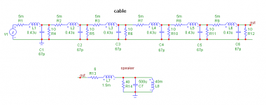
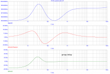
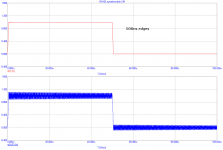
Tried some simulations. I can see nothing but lumped circuit dependent low frequency amplitude deviation (5/1000 of input amplitude) and corresponding phase and group delay deviations. Sorry, no reflections for 10kHz wave. But yes, when such circuit is driven with square, we can se HF reflections, as expected. But such reflections begin to happen above 1MHz.
Attachments
Last edited:
Can't answer this without it's precurser.No, not 'despite' but 'because'. Obviously an LC circuit will have a frequency-dependent response if it is loaded with a frequency-dependent impedance.
you said:
Delays' will be similar on the two channels. Any difference will primarily result from speaker pair mismatching, which will have frequency response implications anyway.[/quote]
It is NOT speaker pair mismatching being discussed here. Why you pulled that out of thin air is beyond me. Other than obfuscation tactics, that is.
What I believe I am claiming? No, it's been clear from the very beginning that you've had a bee up your bonnet. You continue to divert, obfuscate, flail about in many different directions, without actually understanding what you are responding to.I now genuinely do not know what you believe you are claiming.
I've explained exactly what I've been saying here, to you on at least two different occasions in the last year or two. Since I had opted here to AGAIN explain what I am speaking about, it would seem that I am insane. As in, no matter how many times I explain the same thing, you again and again flail about without understanding.
If you took the time, you could find this same explanation on this site, by me.
The T-line model predicts that a short cable, when terminated at both ends with an impedance FAR below the line's characteristic impedance, will settle to final value two or more orders of magnitude longer than the transit time of the cable.
The settling time of the system is heavily dependent on the load impedance.
The settling time can easily exceed the timeframe for human ITD discernment.
The settling time has a minima cusp, becoming zero when load matches line. This behaviour is not intuitively obvious when dealing with a lumped model large enough to simulate an actual line at audio frequencies.
A t-line model easily predicts the settling time LOWER bound, as I've been using the hf impedance, with the added caveat that cable audio impedance rises due to the inclusion of R and G, and it's prop speed lowers for the same reasons, making the final settling time even worse than the hf model would predict.
I can predict the settling time that Scott generated using a 200 element LC construct simply by using the line to load ratio and a simple t line model.
Wrong again.. I state that the settling times rise above the levels at which humans have discernment.You say that these effects are audible due to inter-channel delays
I point out how to use a speaker pair to determine if the overall system response rises to a level of audibility. And I do so while including the confounders that can affect the discernment, and what steps are necessary to remove or control those confounders.
Stop creating your own self serving history.
You need to learn more about how we localize, as your conceptual understanding here is quite challenged. Your inaccurate statement is based on the assumption that we are listening to a monophonic signal., yet in a matched system the delays would be the same in each channel and therefore inaudible
WE???You keep making claims about these time delays but we can't pin you down.
You mean you. You do not yet understand, but that hasn't stopped you. Your "we" claim is a standard internet argument ploy, didn't work.
Then I guess it's odd that using an rf bridge shows the reflection at 10Khz, no?? You know, actual hardware??Tried some simulations. I can see nothing but lumped circuit dependent low frequency amplitude deviation (5/1000 of input amplitude) and corresponding phase and group delay deviations. Sorry, no reflections for 10kHz wave. But yes, when such circuit is driven with square, we can se HF reflections, as expected. But such reflections begin to happen above 1MHz.
Be careful of GIGO sims.
Go back and look at what Scott did. Then examine the graph I posted a while back..
edit: Added the graph to my gallery so that nobody has to search the thread. Haven't created a new album for the topic yet.
jn
Last edited:
What noise? This is an enginnering problem, high quality match terminated systems exist for far more stringent applications. The pre-amp output is already a line level signal and the source and load can be made arbitrarily well behaved at audio frequencies.
The cable will pickup noise, the expensive ones sound better because of their noise rejection due to topology and Shielding. the biggest differences are heard on the long cable runs vs short .
Setup your system and start switching cables you can measure your findings......
Tried some simulations. I can see nothing but lumped circuit dependent low frequency amplitude deviation (5/1000 of input amplitude) and corresponding phase and group delay deviations. Sorry, no reflections for 10kHz wave. But yes, when such circuit is driven with square, we can se HF reflections, as expected. But such reflections begin to happen above 1MHz.
Interesting ....
Why does it have to be expensive cable, there are plenty of cables that will do the job without costing an arm and a leg.The cable will pickup noise, the expensive ones sound better because of their noise rejection due to topology and Shielding. the biggest differences are heard on the long cable runs vs short .
As to shielding, I would say that a lot of high end audio, tailored for audiophiles and some of the ideas promoted (such as taking the shield connection of a single ended cable to some system star point) are some of the worse for EMC immunity. One example where the high end cable claims were disputed:
ASA Adjudication on Russ Andrews Accessories Ltd - Advertising Standards Authority
Calm down, jn. I am not employing any tactics, other than trying to understand what it is you are saying and why you appear to be able to agree with me and disagree at the same time on what appears to me to be the same point.
Unfortunately I don't have time right now to go through your post 46764 but I will, possibly tomorrow.
Unfortunately I don't have time right now to go through your post 46764 but I will, possibly tomorrow.
Calm down, jn. I am not employing any tactics, other than trying to understand what it is you are saying and why you appear to be able to agree with me and disagree at the same time on what appears to me to be the same point.
Unfortunately I don't have time right now to go through your post 46764 but I will, possibly tomorrow.
Regardless of your stated intent, or even what you are truly trying to do, you have enlisted typical internet argument tactics.
You need to understand what was written. You are failing to do that. You have tainted all you see based on your erroneous, early on misconception that a t-line analysis is useless given the wavelengths. Since that initial statement, you've missed the boat. You've failed to read, so now try to state that I'm only now beginning to understand, whereas I've stated concepts and understandings all along. You ignored them.
As for your understanding of audio, two channel reproduction and soundstage imaging, if you wish to speak on that topic, I recommend you take some time off to understand it.
It only requires geometry, the speed of sound in air, the head is 6 inches wide, and use spherical wavefronts. A line array expands too gently and in only one axis, a planar doesn't expand.
jn
Last edited:
One odd note: Why is the 200 unit sim lowering it's ring frequency with time, and why is it becoming less damped with time?
jn
Don't know, I made a subcircuit and cut and pasted 200 in series (actually was quite fast). Our simulator allows turning off all variable saving except a few chosen, most of the simulator time is in saveing all the variables as C++ objects (in our case adi_waveforms).
I already said we agree but with the observation that lumping the L/C's at the source gives EXACTLY the same answer without the reflection jaggies. I suspect the signal could be fixed with a simple all pass phase network.
BTW Bateman was wrong complex impedances are fine, the extended Smith chart for lossy lines is well covered in good texts. The reflection coefficient then is bounded by 1 +- sqrt(2) not +-1. Correcting this does little for his real concerns. OTOH if his wrong reflection coefficient agrees with his bridge maybe some "ED" school is in order.
EDIT - I'm set up to try some of those speaker tests this weekend.
Last edited:
Don't know, I made a subcircuit and cut and pasted 200 in series (actually was quite fast). Our simulator allows turning off all variable saving except a few chosen, most of the simulator time is in saveing all the variables as C++ objects (in our case adi_waveforms).
It looked weird. I've been racking my brain trying to think of any physical reason why the ringing freq and damping would change over time. The most I could think of was that the wire resistance is lowering the slew rate of the leading edge, so the energy hitting the discontinuity has lower frequency content...and the lower freq content doesn't get controlled as fast, hence the lower damping rate.
My expectation is that as time goes on, the lower frequency attributes of the cable will change the waveform because the characteristic z is rising with time. Something I will continue to ponder.
I didn't say we disagreed..I already said we agree but with the observation that lumping the L/C's at the source gives EXACTLY the same answer without the reflection jaggies.

BTW Bateman was wrong complex impedances are fine, the extended Smith chart for lossy lines is well covered in good texts. The reflection coefficient then is bounded by 1 +- sqrt(2) not 1. Correcting this does little for his real concerns.
I wasn't so concerned about his statements on that. Honestly, I'm more interested at this point in pure resistances as loads for the t-line stuff. I don't think a smith chart is going to work very well at these frequencies. I'm still trying to figure out how to go .0001 radians on the chart..my pencil lead is thicker than that.
jn
More specifically, time difference caused by variation of the load impedance.
Vol. II Para. 261.“The Reflection Coefficients in terms of the Terminal Resistance Operators”
Para. 262. “Cases of Vanishing or Constancy of Reflection Coefficients”
It looked weird. I've been racking my brain trying to think of any physical reason why the ringing freq and damping would change over time
If Scott wants to change the inductance value a little in all the 200 units, run the sim and observe the ring frequency’s change with time, and it’s damping with time (after Heaviside Vol. II para 238)
George
That'll change the cable Z and the prop velocity.If Scott wants to change the inductance value a little in all the 200 units, run the sim and observe the ring frequency’s change with time, and it’s damping with time (after Heaviside Vol. II para 238)
George
The small ring at the end of each step looks more like a very small parasitic inductance at the load.
jn
So I went to Home Depot for some RG-8 tonight, no dice.
It did get me thinking about connectors for it, I could put coax connectors on my monoblocs as I have not drilled the holes yet for binding posts.
I would have to really look as I am not familiar with what is available, but this looks like something that could be used as a binding posts?
Amazon.com : AIR802 TNC Jack (Female) Connector for RG8, AIR802 CA400, Times Microwave LMR400, Belden 9913 or Equivalent Size Cables : Coaxial Video Cables : Electronics
Amazon.com : AIR802 N Plug or Male Clamp Style Connector for RG8, AIR802 CA400, Times Microwave LMR400, Belden 9913 and Equivalent : Electrical Clamp Connectors : Electronics
I could make a round plate to cover the binding posts on my speakers and put some connectors on that and as well.
I could probably do the whole deal for $20-$30 plus ship, which isn't bad when you consider that includes binding posts. Assuming I find soemthing suitable in that price range.
Is anyone here using RG-8 binding posts?
I Can see that you are referring to boutique cables which sound diferent because they "alter" the sound. What you may not know is that even ordinary cables sound different, so the question is which one "alters" the sound?
What mostly makes the cables sound different is the material they are made of. Fifteen years ago all cheap cables were made of copper, now most are made of aluminum. Copper and silver sound completely different. Then between coppers, there's purity.
Several posts ago Frank posted about how two cables which sound different became "similar" after they were soldered to both ends. Why is that? That's because the material of the "plug" is "critical" (often the weakest link).
If I'm not mistaken, boutique cables (power cord for example) use rhodium for the plug.
I think some cables have different resistance, but I don't think it is this resistance differences that matters (or could be if it resonates with L and C) because the sound can be fatiguing with some cable (resistance alone should not be responsible with fatiguing sound). Aluminum tends to be fatiguing and may be flat foil tends to be fatiguing as well. Surprisingly, I have 2.4mH flat coils from Intertechnic which looks like aluminum, but sound good in one of my speaker.
Pure conjecture by yourself with no actual testing done objectively. I don't think you have a clue as to the "sound" of cables. Wishful thinking on your part. Yes look into R, L and C as to the "whys" some cables sound "different" also known as being faulty. If a cable can alter the sound then it can be measured. It's not magic.

Would terminating the speaker end of the cable with something like 0.1uf film and 10 ohms 2 watt metal oxide be good practice ( especially for speakers with dome tweeters whose impedance will rise as frequency increases above the audio band. I realise there will be an ideal terminatiion for each system , but it will vary by amplifier type, cable type length, how the cable is layed out to the speaker, and the speaker type itself.
Should or do speaker manufacturers include these rf terminations inside their speakers?
Should or do speaker manufacturers include these rf terminations inside their speakers?
Vol. II Para. 261.“The Reflection Coefficients in terms of the Terminal Resistance Operators”
Para. 262. “Cases of Vanishing or Constancy of Reflection Coefficients”
If Scott wants to change the inductance value a little in all the 200 units, run the sim and observe the ring frequency’s change with time, and it’s damping with time (after Heaviside Vol. II para 238)
George
I think this is length quantization errors, if I halved everything and made 400 sections this ringing frequency would double. In the limit it vanishes.
- Status
- Not open for further replies.
- Home
- Member Areas
- The Lounge
- John Curl's Blowtorch preamplifier part II