http://panasonicelectricworksuk.files.wordpress.com/2013/02/modern-relay-technology_smaller.pdfThe contacts are shielded from the magnet.
Original SDS (google Hans Sauer) datasheets include drawings of the inside.
(nitrogen purged&sealed, capacitance under 1pF, typical thermal voltage < 1µV)
Jacco, thanks for that, lots of very good information.
Dan.
Ok, good point perhaps, 10 uA is 1V into 100K.Hmmm ... looked at the spec. sheet of the relays Dan linked to and Panasonic's more comprehensive technical rundown - just in case I missed something the first time around ...
These are the sort of things that don't inspire confidence:
Min switching capacity: 10uA ("This value can change due to the switching frequency, environmental conditions, and desired reliability level, therefore it is recommended to check this with the actual load")
So much for femto amps ...
This is the sort of thing that somewhat undermined my belief that relays were up to it, the first time round ...
My point was to bring up the usefulness of bistable relays....I have never heard of them mentioned in discussions around here.
My interest in them is that coil excitation currents can be removed once the desired setting is obtained....this will eliminate an electromagnetic field that may have a subjective audio influence....then again maybe not ?.
Jacco says that the magnetic circuit is shielded....maybe the permanent magnet causes a different subjective influence....then again maybe not ?.
It would be very simple to setup a processor to manage a power up sequence that cycles all relay contacts multiple times to help to ensure optimal contact characteristics.
Dan.
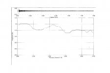
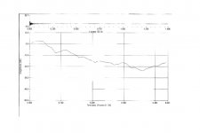
JN: No - think it over. Blue channel is an inductive voltage drop on cable shield. Yellow channel shows what is in fact at the end of the coaxial cable - it is not that simple as voltage drop across the shield. That's how coax works. The other cable is a poor audio non-coax structure, then the shield current reflects in output voltage. Many 'audiophile' cables behave this way.
My statement was in fact related to the secondary path of current in the right hand side coax probe.
You should have explained that you were demonstrating the problem that arises, I just looked and said there's trouble in Oz.
I wrestled with this exact issue when trying to physically measure what's going on in coax/wire systems. The problem is the second scope channel tends to provide a grounding path if I try to use it to view the other end of the coax. I've solved this by either going differential, or making the measurement at only one physical location.
In the past, I've had issues with simu's as well, they didn't handle the quickly changing currents properly with respect to the slower ones.
jn
Pavel did almost the same demo as Van Doren except it is drawn to show the input cable and the output is measured essentially automatically differentialy!
I know. My gut reaction was you can't do that because it's bad EMC practice.
Obviously, you agreed.
It is important to detail the context of a test as presented. This is one problem I have with you, the "guessing games".
jn
The situation is similar as when you connect DVD player (with SMPS power supply) to the amplifier through standard single ended link cable. Fast current glitches will flow through the cable shield with very similar effect that I have shown. That's the way most people have it connected, through mediocre cables.
It is important to detail the context of a test as presented. This is one problem I have with you, the "guessing games".
jn
Pavel’s schematic seems simple but in conjunction with the screenshots, it’s not . With such a test signal, I would say that screenshot results depend on many more fine test jig physical implementation details, not only on cable type.
Pavel is a gamer too
")
George
>Edit:
The situation is similar as when you connect DVD player (with SMPS power supply) to the amplifier through standard single ended link cable. Fast current glitches will flow through the cable shield with very similar effect that I have shown. That's the way most people have it connected, through mediocre cables.
Pavel, like I wrote above, there are similarities but it is the small implementation details that make the difference and not only a mediocre (your word) cable.
George
Last edited:
In case there is no poor soldering and dirty connectors, the result depends mostly on cables used. I have very similar results for RG58 with BNC's and for another 50 ohm (thin) coax with good RCA's (and RCA-BNC adapters). Poor cables with wound shielding have inductive peaks as in the case of that Yamaha cable.
This is one problem I have with you, the "guessing games".
jn
In this thread, this comment applies often. Guessing games... tedious and unnecessary.
In this thread, this comment applies often. Guessing games... tedious and unnecessary.
I have enough problems guessing what I'm saying, nevermind others.
jn
This is one problem I have with you, the "guessing games".
jn
I try to present the information in a simple manner. The issue is common background. There are many things I consider obvious that surprise me when others don't
For example this past discussion on reed relays. A reed relay uses a bent reed that straightens out when inside a coil generated magnetic field. This implies the best reeds are magnetic. (A loose term.)
Now as I assume you know when you pass a current near or through a ferrous metal path there is distortion created. This is dependent on the current flow. So while a reed relay make be just fine at femtoamp levels in a circuit where distortion of -100 db does not matter that is not the same as milliamp levels where -100db distortion does matter.
Then there is the issue of what level of distortion matters. It is well documented that -40 db of distortion of a second harmonic is not an issue. It is also well documented that with carefully selected tones -100 db between them is detectable. Now when you throw in the spectrum of music where the energy really does roll off by about 3 db per octave from 125 hertz and up it should not be surprising that under some circumstances spurious harmonics or difference tones can be detected at levels of -115 db or even more.
Even more complicated is the issue that not only does electricity require a complete path (circuit), but current flow creates a magnetic field that also requires a return path. As most folks are only looking at circuit theory to explain issues that misses the issues that circuit theory is a simplification of current/voltage behavior and completely ignores "magnetic" and "capacitive" issues.
So no I will never be able to give complete information for everyone in describing issues.
In practical application I can't even begin to approach acoustic issues due to the almost complete lack of even basic knowledge.
So now I present a classic acoustics problem to illustrate the point. Attached are before and after reverb time curves of a church with 565,000 cubic feet of volume and 63,000 square feet of surface area. So how many sabins of absorption at 125 hertz are in the room before treatment and how many after?
Attachments
Not to say measurements are Everything --- however, relays are used in the most sensitive low signal level places.... even in distortion measuring equipment by Audio-Precision, H-P, ShibaSoku and several others to incredibly low distortion levels... well below -140dB. So good relays do exist.
THx-RNMarsh
THx-RNMarsh
I try to present the information in a simple manner. The issue is common background. There are many things I consider obvious that surprise me when others don't
I can easily post some "things" up here that nobody else on the planet will understand which I would consider obvious.
The posts where somebody puts up something without a clear and concise contextual explanation, then ask "well, what's right or wrong with this test or schematic, or waddya think.. isn't how to do it on a web forum.
That's what I'm speaking about.
jn
For example this past discussion on reed relays. A reed relay uses a bent reed that straightens out when inside a coil generated magnetic field. This implies the best reeds are magnetic. (A loose term.)
It does not imply it at all. It means that the physical mechanism tries to reduce the path reluctance. Non magnetic materials will not do that.
It is quite easy to make a reed which uses a magnetic material to provide the impetus for forcing a non magnetic leaf to contact.
jn
In case there is no poor soldering and dirty connectors, the result depends mostly on cables used. I have very similar results for RG58 with BNC's and for another 50 ohm (thin) coax with good RCA's (and RCA-BNC adapters). Poor cables with wound shielding have inductive peaks as in the case of that Yamaha cable.
Inductive peaks spell current pulse traffic.
The cable shield quality will exacerbate the results of an existing problem in the DVD/preamplifier combination ground loop/signal return issue.
Is the DVD’s smps return pin directly grounded? How and where?
Is it floating wrt chassis? Is DVD’s output circuit unintentionally (strays) or intentionally (capacitor from shield to chassis) capacitively coupled to chassis?
Ditto for the preamplifier.
Ditto for the RCA or BNC receptacles.
Is the DVD/cable/preamplifier combination problemloss when functions in isolation but becomes problematic due to the connection of a grounded oscilloscope in between (or a grounded amplifier downstream)?
Do I sound awfully jnnian ?
George
Last edited:
Do I sound awfully jnnian ?
George
Oh YOU are a troublemaker...
You vill pay for your insolence..
jn
How about everybody getting more serious on this thread? Cables are problematic. That is our experience. Why, specifically, is sometimes debatable, BUT they do not always follow the simple model that most engineers like to use. This is being shown here today. Let's keep on target, so that we can be more aware of potential problems.
Oh YOU are a troublemaker...
You will pay for your insolence..
jn
Are you a prophet, a medium or what?
How did you know what would come up 3 minutes later?
How about everybody getting more serious on this thread? Cables are problematic. That is our experience. Why, specifically, is sometimes debatable, BUT they do not always follow the simple model that most engineers like to use. This is being shown here today. Let's keep on target, so that we can be more aware of potential problems.
George
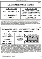
So then, what we should be discussing is the bottom drawing of page 9 of the 2004 Tom Van Doren lecture series. It details how the ground current goes when two paths are available to it, one being a coax shield.How about everybody getting more serious on this thread? Cables are problematic. That is our experience. Why, specifically, is sometimes debatable, BUT they do not always follow the simple model that most engineers like to use. This is being shown here today. Let's keep on target, so that we can be more aware of potential problems.
I couldn't seem to copy the single drawing of the pdf, perhaps George could?
Thanks, John
So then, what we should be discussing is the bottom drawing of page 9 of the 2004 Tom Van Doren lecture series. It details how the ground current goes when two paths are available to it, one being a coax shield.
I couldn't seem to copy the single drawing of the pdf, perhaps George could?
Thanks, John
http://www.ewh.ieee.org/r5/denver/rockymountainemc/archive/2004/October/Experimental_Demo.pdf
IMO the damage is done. Pavel spelled the magic words: “mediocre cables”
George
Attachments
- Status
- Not open for further replies.
- Home
- Member Areas
- The Lounge
- John Curl's Blowtorch preamplifier part II