 have I put correct parameter?
Hi All,
I'm almost done my build and I have a few questions before I try powering it up. First let me say I used the first version of the BOM, on it it has R7 listed as a 2K pot and R8 listed as a 500R pot, and this is what I have currently installed in my boards. The second version of the BOM shows both R7 and R8 as 2K pots. Reading this great build guide and looking at the pics I noticed that R8 is not a pot but a single resistor, and although the guide speaks to adjusting the DC offset (R27) and the bias (R7), it says nothing of the R8 adjustments for the LTP.
Should I replace R8 with a fixed resistor ? If so what value should I use ?
Or should I leave the 500R pot for R8, and if so what value should I adjust it to ?
Thanks,
PJN
PJN
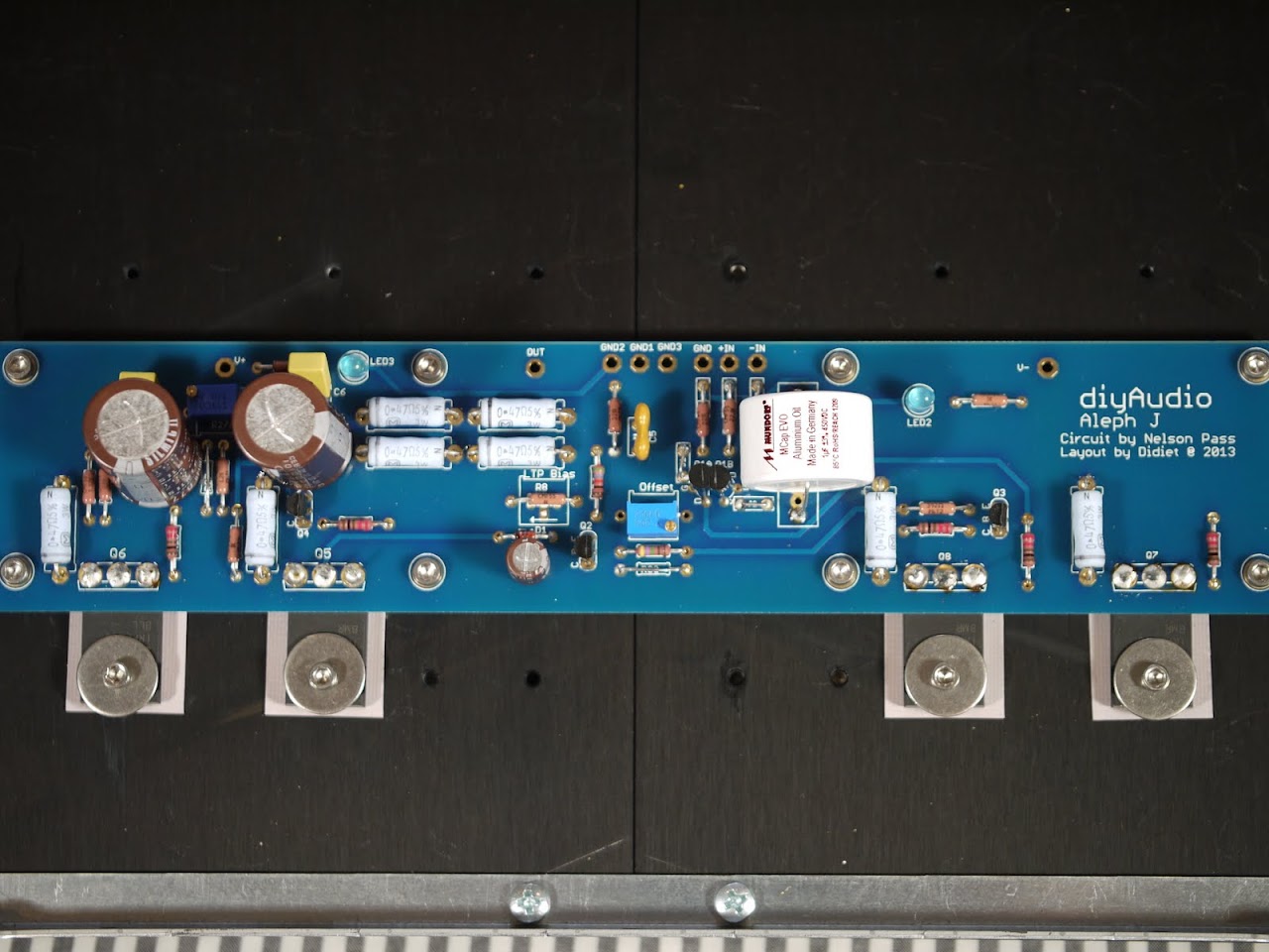
I noticed that R8 is not a pot but a single resistor, and although the guide speaks to adjusting the DC offset (R27) and the bias (R7), it says nothing of the R8 adjustments for the LTP.
R7 is the DC offset adjust - it's nominal value is 1K, so use a 2K pot and set to 1K for initial power-up.
R27 is the AC gain of the Aleph CCS, which also adjusts bias. It's nominal is 68K, use a 100K pot and set to 68K
R8 is part of the input LTP current source, it's nominal is 1K, BUT as the bulk of the operating point of that CCS is set by the zener, just use a 1K resistor in R8 and don't worry about it.
Thanks 6L6, I was about to '+1' that question. I followed the BOM too, and have the pot at R8.
Today I got over to a friends shop to drill the hole for the front panel switch, and holes on the back panel for balanced input jacks, and a switch to do the short for single ended jacks.
A question though. Hook the pos or neg out to the RCA jack? I have figured to short the other to ground with single end (RCA) use.
Some finished parts (Aleph J)
Was lucky to spend some time at a friends shop with a drill press, and drilled out the switch hole on the front panel, and some work on the back panel yesterday. The case work is strongly on the way.
I assembled the heatsinks for the 5U chassis and mounted the 2 amp board, and will post them, as they are done.
I noticed the C4 caps were missing only today as I was mounting to the heatsink.
Here is a pic of the small switch board, and transformer:
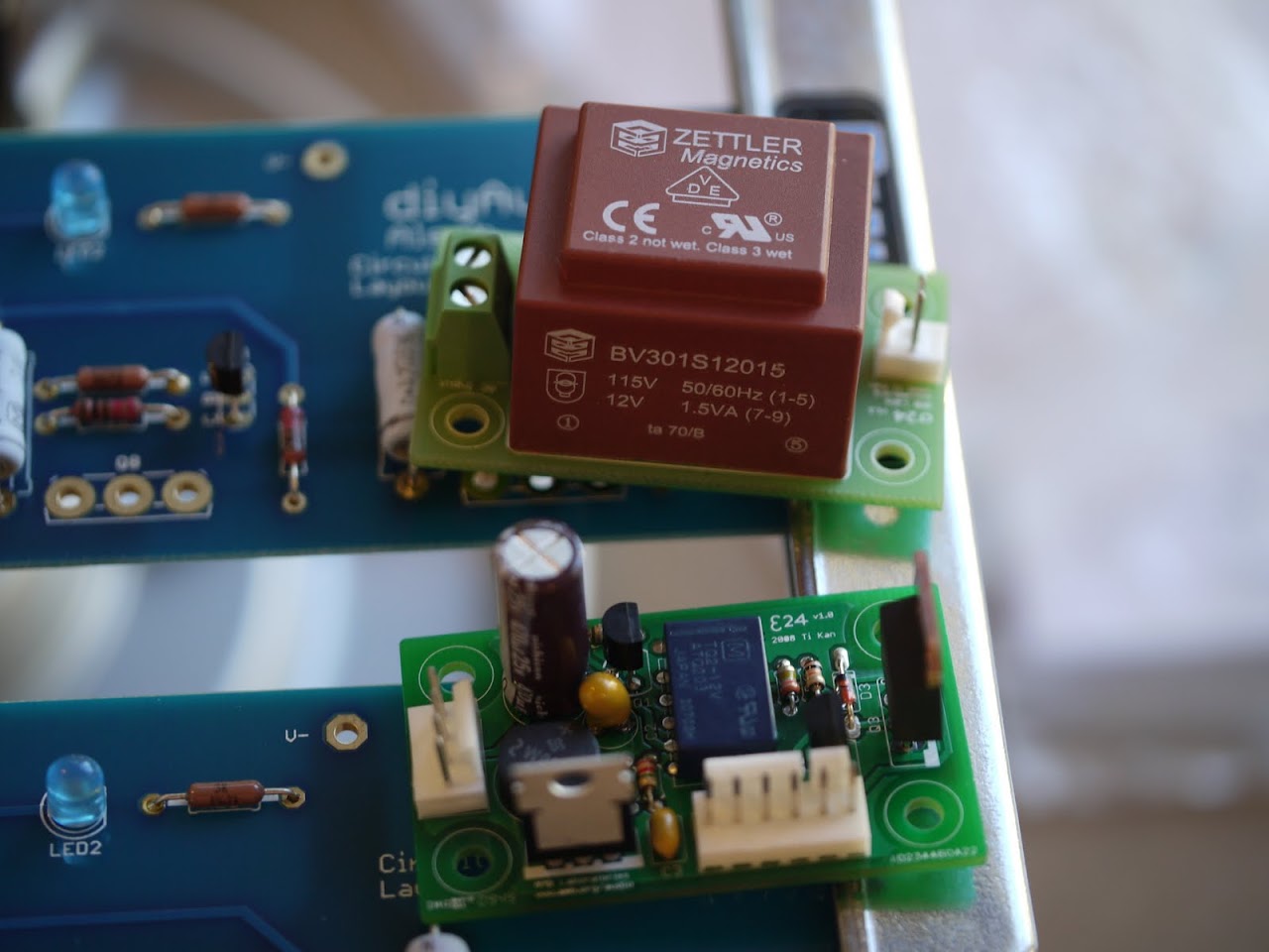
(this allows use of a momentary button switch on the front panel, and only small DC going to and from the switch)
Was lucky to spend some time at a friends shop with a drill press, and drilled out the switch hole on the front panel, and some work on the back panel yesterday. The case work is strongly on the way.
I assembled the heatsinks for the 5U chassis and mounted the 2 amp board, and will post them, as they are done.
I noticed the C4 caps were missing only today as I was mounting to the heatsink.
Here is a pic of the small switch board, and transformer:
(this allows use of a momentary button switch on the front panel, and only small DC going to and from the switch)
Last edited:
Thanks 6L6!
I replaced R8 with 1K resistor in between the shots, and have set the other 2 pots accordingly.
Next part of work will be mounting the back panel parts.
I am waiting on a soon to arrive shipment with some riser panels to play around with transformer/diodes/PSU board placements. It was waiting on the soft start board before shipping, but is on the way now. I am considering the soft start board, but want to see if it will complicate things too much, or be hard to fit in cleanly.
Switch board has small relay to turn on big relay, which would fit into the "switch" on the soft start board, with its own relay... and then the connector strip with inrush protectors.
Save the soft start board for a bigger amp and just use the CL-60 thermistors in the primary circuit.
Which PSU board are you using? Try to keep it together if you are using the new v3 universal. It will always be quieter if it's one piece.
I like the panel switch relay. Are you using a lit 'vandal-proof ' switch?
Which PSU board are you using? Try to keep it together if you are using the new v3 universal. It will always be quieter if it's one piece.
I like the panel switch relay. Are you using a lit 'vandal-proof ' switch?
the switch circuit is populated with the omron small relay to turn off when the sinks get too hot. if your not using this, you should jumper the two input wires t1-t2 to by-pass. the big switch relay is offboard and is activated through the hexfet on button press event
Last edited:
Yes to vandal proof Bulgin momentary switch (has built in LED). Ok on holding off on soft start.
V3 boards separate already, but have big jumpers ready to go. Using bridge diodes, not the ones on the V3 PSU boards.
I do have a large solid state relay for the switch board to run. I will be shorting out the thermistor pins.
V3 boards separate already, but have big jumpers ready to go. Using bridge diodes, not the ones on the V3 PSU boards.
I do have a large solid state relay for the switch board to run. I will be shorting out the thermistor pins.
Save the soft start board for a bigger amp and just use the CL-60 thermistors in the primary circuit.
Just to prevent someone get this wrong - this greatly depends on
both tranny size and capacitance. With e.g. 500 VA + 250 mF I'd
prefer a soft start over a thermistor.
Kudo's to 6L6....!
Jim (6L6)..... I haven't spent much time this last year "hitting the Pass forums", but I wanted to extend major kludo's for your build thread postings. Stellar photography, clear-cut explanations and directions (and your soldering technique has become exceptional!). You're doing a great job for the Pass DIY community, and I just wanted to offer my appreciation for the job well done. It takes your time and committment to make this happen....
P.S. I'm thinking an F-5 Turbo will be in my future--as soon as I finish the turbo's in my car....
Jim (6L6)..... I haven't spent much time this last year "hitting the Pass forums", but I wanted to extend major kludo's for your build thread postings. Stellar photography, clear-cut explanations and directions (and your soldering technique has become exceptional!). You're doing a great job for the Pass DIY community, and I just wanted to offer my appreciation for the job well done. It takes your time and committment to make this happen....


Jim (6L6).....I wanted to extend major kludo's for your build thread postings. Stellar photography, clear-cut explanations and directions (and your soldering technique has become exceptional!). You're doing a great job for the Pass DIY community, and I just wanted to offer my appreciation for the job well done. It takes your time and committment to make this happen....
+1
- Home
- Amplifiers
- Pass Labs
- Aleph J illustrated build guide