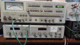
Here is something to know..... if you buy used off eBay (or other place) an HP 339A being sold for 'parts only' and just use the oscillator/generator, it can provide a wide range of freqs - cheap.
Shown are a couple examples with mild tweeking of the osc it will produce low distortion well below .001% or -100dB (IC changes, cap changes and trim adjust). Here are a couple put thru a QA400 FFT:
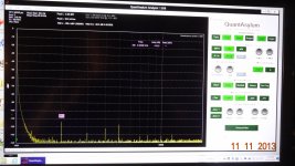
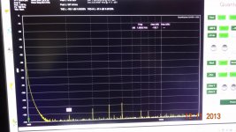
Not as good as what these guys are proposing for DYI.... just something to think about for less ambitious demands than we have.
Thx-RNMarsh
Shown are a couple examples with mild tweeking of the osc it will produce low distortion well below .001% or -100dB (IC changes, cap changes and trim adjust). Here are a couple put thru a QA400 FFT:


Not as good as what these guys are proposing for DYI.... just something to think about for less ambitious demands than we have.
Thx-RNMarsh
Last edited:
comparing
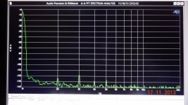
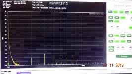
Well, I put the same HP-339A oscillator output to the QA400 and then to the AP 2722. Get two different data. The input level is .7v in each case.
[I had tuned the 2H to be minimum... then I can notch out the 3rd with a rejection filter and get basically a -130dB source... only mild mods done to 339A.]
Next would be to do same level thru a notch and then the Qa400 and see how close it is to the AP2722.
Thx-RNMarsh


Last edited:
A good source of manuals for out-of-print test equipment can be found here:
www.ArtekManuals.com
Thx-RNMarsh
www.ArtekManuals.com
Thx-RNMarsh
Where is that 3H coming from ?
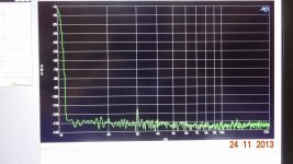
With different opamp for osc (1468) and 49710 osc output opamp and a few other 1468 throughout the unit --- I can null the 2H to below the noise floor and no other harmonics in view EXCEPT there is still the 3H and it is approx. same level no matter which opamp or even which 339A unit. I think it must be a passive part like another pot/control.... maybe the osc freq dual-ganged control/pot. Will be great when that stubborn 3H is also gone below the noise floor.
Thx-RNMarsh
With different opamp for osc (1468) and 49710 osc output opamp and a few other 1468 throughout the unit --- I can null the 2H to below the noise floor and no other harmonics in view EXCEPT there is still the 3H and it is approx. same level no matter which opamp or even which 339A unit. I think it must be a passive part like another pot/control.... maybe the osc freq dual-ganged control/pot. Will be great when that stubborn 3H is also gone below the noise floor.

Thx-RNMarsh
If I read your plot the noise floor of the measurement is -130. Is that source, analyzer or measurement settings? to really see the harmonics I go to a narrow band setting that lowers the displayed noise a bunch. With the 725 I can get below 160 dB pretty easily with a 3V source.
yes, I know....
All extensively covered under the 339A distortion analyzer thread. But -130-135dB is fine for simple changes. I will look into the cause of the 3H though. If I can get that down into the noise then I'll press further to look lower at the thd residual.
-RNM
All extensively covered under the 339A distortion analyzer thread. But -130-135dB is fine for simple changes. I will look into the cause of the 3H though. If I can get that down into the noise then I'll press further to look lower at the thd residual.
-RNM
Also see www.Moorepage.net for a scratch built osc based on 339A circuit. [And R.Moore's thread here about that circuit project] You can see the thd results and which opamps he used.
THx-RNMarsh
THx-RNMarsh
2H = -132dB
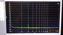
Ok Just for you, Demian -- I pushed the A-P a little harder - to remove more of the 339A generator noise and now you can see the 2H is at approx. -132dB
You can see a little 5H at -135dB. The 3H is still "high" at -117dB.... working on that when I have time.
A-P says the THD+N = .0003_%
Thx-RNMarsh
Noise floor is from the external gen -- the 339A.... -130 to -135 and some units to -140dB.
-RNM
Ok Just for you, Demian -- I pushed the A-P a little harder - to remove more of the 339A generator noise and now you can see the 2H is at approx. -132dB
You can see a little 5H at -135dB. The 3H is still "high" at -117dB.... working on that when I have time.
A-P says the THD+N = .0003_%

Thx-RNMarsh
Last edited:
Ok Just for you, Demian -- I pushed the A-P a little harder - to remove more of the 339A generator noise and now you can see the 2H is at approx. -132dB
You can see a little 5H at -135dB. The 3H is still "high" at -117dB.... working on that when I have time.
A-P says the THD+N = .0003_%
View attachment 384574
Thx-RNMarsh
Could you please stop posting distortion measurement results where you have routed the input signal directly to the ADC of your SYS-2722? This is very misleading, as the ADC does not have sufficiently low distortion for measurements at the levels you're trying to achieve. You need to switch in the analog notch filter. Several people have repeatedly pointed this out, and I have even sent you setup files showing the correct configuration. No excuse, really.
BTW, there's also an easy function to export your graphs to a standard graphic format (e.g. PNG). This would make your attachements smaller and much better readable...
Thanks,
Samuel
Hi Samuel.
Hows the oscillator coming along?
I'm still working on the complete schematic which I hope will be the final one. I think I have clarified all major design issues, but there are lots of details to work out (calculating resistor values for the output driver etc.). It is clearly a very complicated design, more than 20 pages.
Samuel
I'm still working on the complete schematic which I hope will be the final one. I think I have clarified all major design issues, but there are lots of details to work out (calculating resistor values for the output driver etc.). It is clearly a very complicated design, more than 20 pages.
Samuel
Can you use an attenuator that exist already and just scale the values to your needs?
This would save time.
How did the post amplifier work out?
Can you use an attenuator that exist already and just scale the values to your needs? This would save time.
Calculating the basic values is not the main issue. It's more about calculating the required number of series/parallel combinations (to get distortion from power coefficient sufficiently low), transferring them to the schematic and verifying all this.
How did the post amplifier work out?
I presume you're talking about the one I'm using for the notch filters? I didn't do any new revision so far, just mentally sketched a better implementation.
Samuel
Could you please stop posting distortion measurement results where you have routed the input signal directly to the ADC of your SYS-2722? This is very misleading, as the ADC does not have sufficiently low distortion for measurements at the levels you're trying to achieve. You need to switch in the analog notch filter. Several people have repeatedly pointed this out, and I have even sent you setup files showing the correct configuration. No excuse, really.
BTW, there's also an easy function to export your graphs to a standard graphic format (e.g. PNG). This would make your attachements smaller and much better readable...
Thanks,
Samuel
I'll address the easy ones first --- the graphs are presented in a format which is for my own convenience and I only use jpg. The jpg are 600 dpi and can be blown up and still see details. I use 2 different cpu systems so this works best for me. And, No I don't want to spend time setting up a wireless network for a few pictures for DIY.
The test was primarily redone with just averaging applied to drop the noise from the graph. The 2722 system setup is as A-P tech support advised....
However, I am not trying to get accurate data down really low so much as show I can drop the 2H into the noise with a particular opamp combo for the oscillator.... using only minimum effort. I am not actively working on this 339A anymore. Its done as far as I am concerned. Note_ I have the ShibaSoku 725D to cross check data results if I feel the need to do so.
When there is a signal source generator that is low enough in distortion (like Victors') and I want to measure That units THD, then I'll have to get tighter with the measurements. Maybe then I'll have to use a notch filter.
BTW -- that reminds me of an article I read today -- Jim Williams a few years back did a "microprocessor corrected ADC" which was accurate to 1ppm. I'd like to see something like that done here at DIYAudio Land. I wonder if A-P doesn't do something similar.
Thx-RNMarsh
Last edited:
Calculating the basic values is not the main issue. It's more about calculating the required number of series/parallel combinations (to get distortion from power coefficient sufficiently low), transferring them to the schematic and verifying all this.
I presume you're talking about the one I'm using for the notch filters? I didn't do any new revision so far, just mentally sketched a better implementation.
Samuel
No I' referring to a more resent post on the progress of your project. You mentioned composite design for the oscillator.
- Home
- Design & Build
- Equipment & Tools
- Low-distortion Audio-range Oscillator
