Just to state what I think that means: It means that all of the Fourier components (i.e. at all of the odd harmonic frequencies) still had the correct amplitudes and relative (to each other) phase angles. So the phase angles either had not changed, or, they all had changed by the same constant. So the phase angle change did not vary with frequency. Does that seem correct?
yes, pretty much. Now to the waterfall plot of this type LP/HP crossover --- it will look like what??
Thx-RNmarsh
I don't think I know, any more, what topology is being discussed. Can you point to a schematic?
The one JC is talking about here. When you sum the outputs... what does it look like with a MLSSA test or "waterfall" plot?
Thx-RNMarsh
on axis
Indeed. All of this is good at one point. Real speakers are put into rooms. If you trade off something real and extremely important (polar pattern) for something marginal (square wave response), you're unlikely to get a good result.
Completely agree with SY. The problem is to get acoustic addition work right, in a real room. This means that not just the on-axis addition of the drivers is relevant, but also the off-axis addition. In the case of substractive filters and non-coincident drivers, the off-axis behaviour is dismal.
In the off-axis response, you can easily live with dips, but peaks come back to haunt you. This is what a substractive filter delivers with non-coincident drivers.
On KSTR's point on the need for "drivers EQ'd to flat one decade beyond XO point", I am wondering if that is not overdoing it a bit. Obviously it depends on filter order. Take a 4th order LR filter: one octave below xover, each driver is already down by some 30dB. Any inherent phase shift in the drivers will only be of marginal consequence at that point. Lower orders obviously have more stringent requirements, but even in a 1st order network, I wonder if a tweater xovered at 2KHz would need to be compensated down to 200Hz.
Well, I just got back from the AES in NY. Had a few chats with some of the back room engineering types.
Turns out I made a mistake. I thought the portable loudspeaker test chamber I made was a failure. The committee on loudspeaker measurement thought it was a great design and started a new project. Other folks will follow my plans and build other chambers. If we can get very similar results measuring the same driver in different chambers, then it may become a standard. The idea is that it is not used in place on an anechoic chamber, but as a production line test.
The other bit was when I mentioned that in my systems I do not want flat loudspeaker driver response. So let see who knows why that is actually a bad thing!
ES
Dick, If a filter rings that will show up on a waterfall response. Deliberately ringing a filter was mentioned on your test equipment thread. Properly designed electronic crossovers don't ring. So the most you will see is a fattening of the top line due to phase shift. Now with a passive crossover there will be energy left due to the connected driver. As most drivers are reversible transducers and have mass and springiness they will return late energy. (But you knew that.)
Completely agree with SY. The problem is to get acoustic addition work right, in a real room. This means that not just the on-axis addition of the drivers is relevant, but also the off-axis addition. In the case of substractive filters and non-coincident drivers, the off-axis behaviour is dismal.
In the off-axis response, you can easily live with dips, but peaks come back to haunt you. This is what a substractive filter delivers with non-coincident drivers.
This brings up the issue of near field vs far field. Mark Ureda did a paper where he defined far field as the distance where path length is long enough you no longer have path length difference phase cancellations. That distance is a minimum on axis and goes to infinity where you are off axis so that the drivers are in a line with the measurement point.
Indeed. All of this is good at one point. Real speakers are put into rooms. If you trade off something real and extremely important (polar pattern) for something marginal (square wave response), you're unlikely to get a good result.
The idea is not to trade anyone out , good balance is more acceptable than superiority in anyone , trading a good squarewave for polar pattern will also bring it own problems ..
Completely agree with SY. The problem is to get acoustic addition work right, in a real room. This means that not just the on-axis addition of the drivers is relevant, but also the off-axis addition. In the case of substractive filters and non-coincident drivers, the off-axis behaviour is dismal.
In the off-axis response, you can easily live with dips, but peaks come back to haunt you. This is what a substractive filter delivers with non-coincident drivers.
On KSTR's point on the need for "drivers EQ'd to flat one decade beyond XO point", I am wondering if that is not overdoing it a bit. Obviously it depends on filter order. Take a 4th order LR filter: one octave below xover, each driver is already down by some 30dB. Any inherent phase shift in the drivers will only be of marginal consequence at that point. Lower orders obviously have more stringent requirements, but even in a 1st order network, I wonder if a tweater xovered at 2KHz would need to be compensated down to 200Hz.
You can use conjugates on the tweeter lowpass and still maintain a 6db electrical , like anything else there are tradeoffs ..
This brings up the issue of near field vs far field. Mark Ureda did a paper where he defined far field as the distance where path length is long enough you no longer have path length difference phase cancellations. That distance is a minimum on axis and goes to infinity where you are off axis so that the drivers are in a line with the measurement point.
I can agree with this ...
I would think -
yes. And the question isnt about either sqaure wave or anything like it. Its about GDelay and if the flat GD crossover will have constant decay thru it at the summed output (use a resistive summing network for proof)..... as seen in a MLSSA test thru the crossover.
Surely, some here have MLSSA, as i do, software/hardware to try this....JC at least ought to do the test to know the results... data shown in another dimension. Good food for thought if one wants to know new info and data and views on what we are hearing. I would think.
Thx-RNMarsh
The idea is not to trade anyone out , good balance is more acceptable than superiority in anyone , trading a good squarewave for polar pattern will also bring it own problems ..
yes. And the question isnt about either sqaure wave or anything like it. Its about GDelay and if the flat GD crossover will have constant decay thru it at the summed output (use a resistive summing network for proof)..... as seen in a MLSSA test thru the crossover.
Surely, some here have MLSSA, as i do, software/hardware to try this....JC at least ought to do the test to know the results... data shown in another dimension. Good food for thought if one wants to know new info and data and views on what we are hearing. I would think.
Thx-RNMarsh
Richard, I think that you missed the point: There is NO time or phase information left after an IDEAL subtraction (electrical). The problem is when we depend on acoustical subtraction, that we see the error of our ways.
This sort of crossover has been used in speaker systems for many decades. Often there is a 'filler driver, that fills in the extra information that makes the crossover Transient Perfect.
I don't have a simulation up and running, and if you want a test, you should do it yourself. For example, I have never done a waterfall test, and I don't build speakers anymore, so I most probably will never have the program.
The point that I hoped to make was how complex delays can be cancelled and IDEALLY there is nothing left but the original signal, without even a measurable time delay.
Now, is this an excellent Xover to use. NOT unless you know what you are doing. John Meyer and I made a 3 way version of the TP Xover for a TIME ALIGNED 3 way all horn speaker with some success in 1974. We had FFT measurements that showed that we were very successful. However, in 1975, I tried to use a TP Xover for another speaker, composed of a wide range horn (Emilar) and a 15" Gauss woofer. The TP Xover failed miserably in this case and I went to 3 pole Bessel filters that worked OK. For some reason, 3 pole Bessel filters work better than most filters as far as transient response. This was part of a paper given by Yamaha (I think) in 1975. In a free field, I got an excellent frequency response and a pretty good transient response, but the speaker ultimately proved to be a failure, subjectively. (so much for normal measurements) I have never attempted to build a speaker system since.
The idea is that it is not used in place on an anechoic chamber, but as a production line test.
The other bit was when I mentioned that in my systems I do not want flat loudspeaker driver response. So let see who knows why that is actually a bad thing!
Ed, I wish you good look with the anechoic nanochamber, but I have learned that you can't screw with Mother nature. An anechoic chamber needs to be large, no two ways about it.
Something else is to having a quick production line test. For drivers and even whole loudspeaker systems, this can be done in a much easier way. Take an approved standard, connect the dut in antiphase, put the noses together, and everything that doesn't cancel out is an error.
The question you raise about the desirability of a flat FR in as loudspeaker is an interesting one. Many different answers are valid. As a design goal, it is good. For use in a highly damped room, it's also good.
However, in many other situations, a flat FR is not to be desired. For long throw speakers, you may wish to compensate for atmospheric absorbtion. Speakers placed near boundaries require the bass to be diminished; wide dispersion speakers in a hard room need the mid/high to be cranked down a bit.
In short, you need tone control to adjust any loudspeaker system to the particular situation it is being used. But a loudspeaker with a flat FR anechoically is a good place to start.
I didnt miss the point and nothing you have said is also new to me.
Already did the test, John. [ I'm not asking the question because I do not know the outcome.]")
Suggest doing it to a TP and do it with other topologies and compare.
Hint - It will help add to the understanding of why some didnt sound right even if they had good measured (standard tests) freq or transient response.
Keep an open mind.
Thx-RNMarsh
Already did the test, John. [ I'm not asking the question because I do not know the outcome.]
Suggest doing it to a TP and do it with other topologies and compare.
Hint - It will help add to the understanding of why some didnt sound right even if they had good measured (standard tests) freq or transient response.
Keep an open mind.
Thx-RNMarsh
Richard, I think that you missed the point: There is NO time or phase information left after an IDEAL subtraction (electrical). The problem is when we depend on acoustical subtraction, that we see the error of our ways.
This sort of crossover has been used in speaker systems for many decades. Often there is a 'filler driver, that fills in the extra information that makes the crossover Transient Perfect.
I don't have a simulation up and running, and if you want a test, you should do it yourself. For example, I have never done a waterfall test, and I don't build speakers anymore, so I most probably will never have the program.
The point that I hoped to make was how complex delays can be cancelled and IDEALLY there is nothing left but the original signal, without even a measurable time delay.
Now, is this an excellent Xover to use. NOT unless you know what you are doing. John Meyer and I made a 3 way version of the TP Xover for a TIME ALIGNED 3 way all horn speaker with some success in 1974. We had FFT measurements that showed that we were very successful. However, in 1975, I tried to use a TP Xover for another speaker, composed of a wide range horn (Emilar) and a 15" Gauss woofer. The TP Xover failed miserably in this case and I went to 3 pole Bessel filters that worked OK. For some reason, 3 pole Bessel filters work better than most filters as far as transient response. This was part of a paper given by Yamaha (I think) in 1975. In a free field, I got an excellent frequency response and a pretty good transient response, but the speaker ultimately proved to be a failure, subjectively. (so much for normal measurements) I have never attempted to build a speaker system since.
Last edited:
<snipped>
The other bit was when I mentioned that in my systems I do not want flat loudspeaker driver response. So let see who knows why that is actually a bad thing!
ES
<snipped>
Fletcher-Munson effect? Human sound perception does not have a flat frequency response. But, on a recording, isn't that already accounted for, by the musicians?
But WHERE it might be made flat is also important. If made flat, it needs to be flat in a particular room, rather than in an anechoic chamber. And in a larger venue (and probably in a room at home, too), flattening it on-axis, only, might be not so good. You should probably look at the entire spherical radiation pattern at once, at each frequency, like we do with 3-D antenna patterns for RF. (Or, at the very least, look at the slices of the patterns that point toward where the audience is located, e.g. all azimuth angles for each relevant near-horizontal elevation angle, per pattern, per frequency.)
Do speaker developers have automated spherical-pattern-measuring systems, like we do for RF antennas? We have some little ones, at work, for antennas alone, that will rotate the antenna through 360 degrees of azimuth, repeatedly, changing its elevation angle for each revolution, with a fixed measurement antenna and a network analyzer and a laptop computer, doing full frequency sweeps at each tenth of a degree of rotation in each direction, that then provide exquisite 3-D patterns (and all of the raw data).
The real trick is getting the same type of measurements for an antenna that's mounted on a vehicle. There are facilities we use, for that. But they are BIG, and expensive. Imagine a 15-ton vehicle hoisted onto a tall tower that was made without metal, that rotates, and a measurement antenna that can travel a vertical arc of more than 180 degrees centered around the top of the tower, in the far field, again without using metal in the construction.
Last edited:
There's an interesting discussion about flat response at Is flat frequency response a false ideal?? - Page 2 .
Someone there also mentioned flat timbre response, and stated that the only time you can have both flat timbre response and flat frequency response is if you have flat phase response, and thus, if your phase response is not flat then your frequency response should not be flat if you want flat timbre response (assuming you have a balanced and diffuse reverberant field).
Someone there also mentioned flat timbre response, and stated that the only time you can have both flat timbre response and flat frequency response is if you have flat phase response, and thus, if your phase response is not flat then your frequency response should not be flat if you want flat timbre response (assuming you have a balanced and diffuse reverberant field).
I did, just recently again, true realtime A/B, symmetric slope even order zero interphase allpass XO (Linkwitz-Riley and phase-matched Bessel) with signal phase predistortion to cancel the allpass always did much better than any analog TP, for obvious reasons (at least to me). Zero interphase is the key -- no lobing errors --, analog TP cannot do that (a mathematical constraint) except for D'Appolito-style arrangement.Suggest doing it to a TP and do it with other topologies and compare.
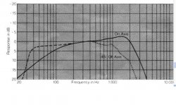
Attached is a frequency response curve of a woofer. Over what frequency range is it useful?
What is the diameter?
- Status
- Not open for further replies.
- Home
- Member Areas
- The Lounge
- John Curl's Blowtorch preamplifier part II