I'm searching for some toroidal type step up transformers with a 50:1 ratio to use with Martin Logan Monolith-III ESL panels and would like to find something that might be more economical than the Amplimo - Plitron step-up transformers. I noticed some of the people on this site are using the inexpensive standard power toroid's with 230V single primaries with 9V dual secondary's for a 50:1 ratio or the 6V dual secondary's for a 75:1 ratio and would be curious to know what model transformers work the best with the 24" X 48" size panels.
I'm thinking of using dual Multi-Comp VTX-146-050-109 toroidal transformers with a 50V 2.78A power rating or the VTX-146-080-109 with a higher 80V 4.44A power rating wired in 230V series and 9V parallel. http://www.farnell.com/datasheets/85993.pdf
.
.
I'm thinking of using dual Multi-Comp VTX-146-050-109 toroidal transformers with a 50V 2.78A power rating or the VTX-146-080-109 with a higher 80V 4.44A power rating wired in 230V series and 9V parallel. http://www.farnell.com/datasheets/85993.pdf
.
.
Attachments
Last edited:
Hi,
Is there a reason like a defect, that You want to replace the originals?
A couple of Years ago a customer asked me to do the same with his Sequel2.
The final result was, that it wasn't worth the effort.
ML's old speakers used vast amounts of equing, up to 15dB of electrical amplitude response. This amount of correction dwarfed any advantage a toroid might have offered. So, I recommended the customer to keep te original transformers and save the money ... which he did.
If You want the toroids to improve matters, it means a whole new design.
It is not the panels that are the pinhole of the old MLs, but the bass systems.
The panels alone would have been capable of seriously better performance with considerably increased efficiency, especially if the whole system would be activated.
But that would of course mean to design a complete new speaker.
So, if You want to keep Your Monolith as is, only tweaking the transformers with toroids will probabely be disappointing. The differences will be very small to nil.
Is there a special reason for a 1:50 ratio here? It is a fine value for panels of capacitance value close to 2nF. 1 nF and 1;75 give a good (impedance) match also. Values in between maybe interploated. 230/7V or 230/8V maybe better choices. Even with large panels I never chose 230/9V.
jauu
Calvin
I like the idea of using toroidal step-up transformers because they have a more efficient design than conventional E or C-core type transformers. The toroid transformers have less leakage flux and therefore they have significantly less leakage inductance. The stock E-core transformers are not as good in my opinion because the cores can get easily saturated and they have a high leakage & magnetic inductance which needs to be compensated for by adding 50W power resistors on the secondary side. Also the stock transformers only use outer part of the coil field on the secondary side because of these limitations. The Plitron's are good toroidal set-up transformers but the output is only rated around 70-watts and there are only three small 22-guage wires for the panels. I'm not certain of the wattage ratting used for the Monolith-III transformers but they have much thicker gauge wire size with a six wire output bridged at the PC board into three sections going to the panels. The ML CLS-II panels are the same size and use two of the same transformers wired in parallel with better results.
I have no problem with increasing the turn's ratio slightly but the panels impedance can dip down below 1-ohm in the 20kHz range which could cause problems with weak amplifier. My present amplifier is rated at 800wpc @ 4-ohms, 1600wpc @ 2-ohms and 2400wpc @ 1-ohm for a limited time basis. I removed the passive crossover boxes and I'm now using an active crossover which has much better results but there's still room for improvement with internal mods.
I also plan to mod the original bias power supply from 2.8kV to around 3.5kV which seems to help improve the sound on the older ML panels. The stock power supply has four 15M resistors for total of 60M-ohms to increase the voltage and lower the amperage to the panels. I plan to drop it down to around 20M and delete the two 1.8K-ohm power resistors which limits the bias power supply transformers voltage output.
If you know of any toroidal transformers that might work well in the 230/7V or 230/8V range please let me know the manufactures part numbers. I have also been considering the Antek brand which has dual 115V secondary windings. Antek - Transformers - Grid View
.
Attachments
Hi,
it is used either for turning off the bias voltage fully or to reduce it to a lower standby value. Iirc the latter is the case here.
As we probabely all know, a ESL panel needs several minutes up to a couple of hours to sound optimally after switch-on. The longer so, the longer it has been off.
If it idles in standby on a reduced bias it comes up much faster, but the tendency to atract dust is lowered.
jauu
Calvin
A pair of Martin Logan electrostats will draw about 5 watts maximum. There is circuitry to turn off the static charge when not in use; however, actual consumption will remain close to the same. The primary purpose of the sensing circuitry is to prevent dust collection on the electrostatic element.I'm intrigued by the "Music Sense" input on the high voltage supply in the Monolith schematic. Is it used to turn the supply on/off and save energy or is there some other function?
.
Attachments
Is there any reason people are using dual primaries & secondary's other than they're easy to find? I was able to find some 230/8V toroids with single primaries & secondary's but they're special order.
What would make the perfect toroid step up transformer for ESL panels? Is there any problem with using the larger size toroids with the 200VA to 500VA rating with the same step up ratio? Also would it help to have a metal core with grain oriented structure and extra shielding with epoxy encapsulation? I'm thinking about having some custom manufactured or make them myself.
What would make the perfect toroid step up transformer for ESL panels? Is there any problem with using the larger size toroids with the 200VA to 500VA rating with the same step up ratio? Also would it help to have a metal core with grain oriented structure and extra shielding with epoxy encapsulation? I'm thinking about having some custom manufactured or make them myself.
Mostly single winding 230V transformer are hard to obtain on this side of the pond.
You may also have a better (lower) stray capacitance figure having one complete 230v winding rather than having two 115v windings wrapped one on top of the other.
A while back I had put one of Antek's AS-1206 through its paces and it seem to fair well to about 4500V of output.
But, this model has an electrostatic shield in it and in my opinion was the cause of its failure.
Try to stay away form these types if you can!
Hence the "AS" types.
Or unwrap the tape and low voltage winding and remove the shield and then put the LV winding back on.
Else DO NOT connect this shield to anything, not ground, not anything.
For two reasons,
#1 the insulation between the shield and the HV winding is thin and weak and may/will at some point cause a breakdown and arc through from the HV winding to the shield burning a few winding's thus shorting them out.
#2 the shield adds more unneeded stray capacitance to the transformer and therefore creates more load for the amplifier.
This Happened to me and I have it documented here,
Testing Your Transformer and Using the Transformer Test Jig
Here is the thread that shows the saturation tests,
A TEST JIG FOR FINDING ESL STEP-UP TRANSFORMER PARAMETERS
Typically you won't gain any significant performance by using a larger core if the HV winding is designed for 2X115v or 230v.
Except maybe only a very slightly lower THD on the low frequency side of things up to to the saturation point due to it having more iron, But I have not done any more tests lately to verify this.
I use 210 watt cores form a different company and they perform the same under identical conditions as the 100watt Antek AS-1206 that I have tested.
Everything is based upon this part of its parameter, and, unless it is designed for a higher voltage a 50,100 and 200 watt cores will have the similar saturation characteristics when it comes to feeding the LV winding.
Increasing the HV winding turn's is the only way to change this.
I had suggested a while back that maybe using one of Antek's HV trnasformere that has multiple HV windings might be a viable alternative and just add your own primary winding.
But it is a rather costly transformer to begin with.
Here is just one such example and may just work right out of the box,
http://www.antekinc.com/pdf/AN-4TK400.pdf
I have never tested one of these so I can't tell you what its stray capacitance and leakage inductance would be as this would determine what your high frequency performance would be.
By using the two 6.3V winding in series for 12.6v and the all of the HV winding in series would yield you a transformer with 1:81.7 step up ratio with good saturation performance down to 150hz or so with a 150 to 200 watt amplifier all in one nice package.
Or even down to the 50Hz to 100Hz range at lesser power levels with the 12v configuration.
By using it in the 6V mode could yield a 1:163.4 ratio with a low frequency point of 300hz.
This would be the nearly same cost of 4 of the smaller Antek AS-0506, But these are shielded types and they don't list the non shield AN-0506 anymore.
They do Have the AN-0206 core at $11 each and these may work just fine as well providing that you are using a crossover of above 360Hz or so depending on the power range of your amplifier.
Hardly any of these combinations will yield you anything good below 300hz anyhow unless you use 8 cores for just one panel.
Except maybe the above AN-4TK400 or something like it.
This is just a suggestion as it has not been tried before to my knowledge, But it may be a good possibility one wanted to give it a try.
They do have a few other cores that may work as well in a similar configuration but do stay away from the shielded "AS" types.
If you wanted to wind your own then you could start with a very large core from Alpha Core quite affordably.
But it is quite tedious to do.
Silicon Steel Toroidal Cores - In Stock
FWIW
jer")
You may also have a better (lower) stray capacitance figure having one complete 230v winding rather than having two 115v windings wrapped one on top of the other.
A while back I had put one of Antek's AS-1206 through its paces and it seem to fair well to about 4500V of output.
But, this model has an electrostatic shield in it and in my opinion was the cause of its failure.
Try to stay away form these types if you can!
Hence the "AS" types.
Or unwrap the tape and low voltage winding and remove the shield and then put the LV winding back on.
Else DO NOT connect this shield to anything, not ground, not anything.
For two reasons,
#1 the insulation between the shield and the HV winding is thin and weak and may/will at some point cause a breakdown and arc through from the HV winding to the shield burning a few winding's thus shorting them out.
#2 the shield adds more unneeded stray capacitance to the transformer and therefore creates more load for the amplifier.
This Happened to me and I have it documented here,
Testing Your Transformer and Using the Transformer Test Jig
Here is the thread that shows the saturation tests,
A TEST JIG FOR FINDING ESL STEP-UP TRANSFORMER PARAMETERS
Typically you won't gain any significant performance by using a larger core if the HV winding is designed for 2X115v or 230v.
Except maybe only a very slightly lower THD on the low frequency side of things up to to the saturation point due to it having more iron, But I have not done any more tests lately to verify this.
I use 210 watt cores form a different company and they perform the same under identical conditions as the 100watt Antek AS-1206 that I have tested.
Everything is based upon this part of its parameter, and, unless it is designed for a higher voltage a 50,100 and 200 watt cores will have the similar saturation characteristics when it comes to feeding the LV winding.
Increasing the HV winding turn's is the only way to change this.
I had suggested a while back that maybe using one of Antek's HV trnasformere that has multiple HV windings might be a viable alternative and just add your own primary winding.
But it is a rather costly transformer to begin with.
Here is just one such example and may just work right out of the box,
http://www.antekinc.com/pdf/AN-4TK400.pdf
I have never tested one of these so I can't tell you what its stray capacitance and leakage inductance would be as this would determine what your high frequency performance would be.
By using the two 6.3V winding in series for 12.6v and the all of the HV winding in series would yield you a transformer with 1:81.7 step up ratio with good saturation performance down to 150hz or so with a 150 to 200 watt amplifier all in one nice package.
Or even down to the 50Hz to 100Hz range at lesser power levels with the 12v configuration.
By using it in the 6V mode could yield a 1:163.4 ratio with a low frequency point of 300hz.
This would be the nearly same cost of 4 of the smaller Antek AS-0506, But these are shielded types and they don't list the non shield AN-0506 anymore.
They do Have the AN-0206 core at $11 each and these may work just fine as well providing that you are using a crossover of above 360Hz or so depending on the power range of your amplifier.
Hardly any of these combinations will yield you anything good below 300hz anyhow unless you use 8 cores for just one panel.
Except maybe the above AN-4TK400 or something like it.
This is just a suggestion as it has not been tried before to my knowledge, But it may be a good possibility one wanted to give it a try.
They do have a few other cores that may work as well in a similar configuration but do stay away from the shielded "AS" types.
If you wanted to wind your own then you could start with a very large core from Alpha Core quite affordably.
But it is quite tedious to do.
Silicon Steel Toroidal Cores - In Stock
FWIW
jer
Last edited:
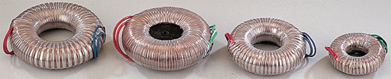
Thanks for the information and all the links above. Do you know if the toroidal O-cores are any more efficiency the standard toroidal cores? It seems if the windings have fewer right angles and shorter spans there would be significantly less inductance.
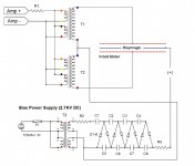
Has anyone tried using the AnTek AN-1212 - 230/12V or the AN-2215 - 230/15V toroids which are the unshielded AN version that could be interconnected to obtain a higher step up ratio? Theoretically the 12V should produce a ratio of around 75:1 and the 15V should be around 60:1 as in the schematic below.
Source page 128: http://home.kpn.nl/verwa255/esl/ESL_English_2011.pdf
.
Attachments
All of the 12xx series of transformer will have the same core size and same amount of turns on its HV winding, only the LV winding turns are changed.
Therefore the 12V LV winding will have twice as many turns a 6V Lv winding and all else stays the same!
A 12V/230v transformer gives about a 1:18.25 ratio and two cores wold give you only 1:36.5 not 1:75, it would take 4 core to get there with 12V LV windings.
In practice, With the transformer I tested I found it to actually be 1:38 for the 6V winding's and of course half that at 1:19 if they were wired for 12V.
For a larger core size your overall turns would be less as they are adjusted for the same 230V at 50hz operating magnetic flux level in the core material.
It would be great if we had the same amount of turns found on a much smaller core on a larger core, but that would be a waste of copper for the range of what they are designed for.
Every time you double the excitation voltage on any particular winding designed for a particular voltage without increasing its turns, you must also double its frequency in order to keep the core from going in to saturation.
Therefore if you increase the voltage at rate X then you must also increase the frequency by the same rate of X.
Using the Plitron 1:50 for example is actually a 17.5v/875v transformer designed for a lowest saturation frequency of 50hz.
jer
Last edited:
I believe that having some O-core toroids custom manufactured will be the best option in my opinion and the expense will be slightly higher with a longer wait time.
You're correct saying the AnTek AN-1212 or AN-2215 toroids would have to be used in a four core setup to get that higher ratio.
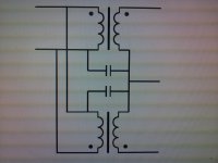
Would you happen to have a diagram, picture or description of how these 230/6V toroidal transformers are wire wound and would it be possible to shorten the 6V section to increase the ratio or rewire the 6V section to lower the overall ratio?
You're correct saying the AnTek AN-1212 or AN-2215 toroids would have to be used in a four core setup to get that higher ratio.
Would you happen to have a diagram, picture or description of how these 230/6V toroidal transformers are wire wound and would it be possible to shorten the 6V section to increase the ratio or rewire the 6V section to lower the overall ratio?
Attachments
No I don't have a diagram as to how they are wound,
I have never had one to take apart and examine either so I can't even explain it for you, sorry.
Yes, you can shorten the LV winding providing you can get the tape off and get to it, as this will take some time because they use a lot of it.
Or you can just add your own winding as I have done here instead,
http://www.diyaudio.com/forums/planars-exotics/161485-step-up-transformer-design-3.html#post2129471
Just remember when you shorten the LV winding you must assure that you use a higher cross over frequency in order to not go into the saturation range of your core.
I explain all of that in the above thread.
For an example here is the saturation vs turns chart I made for the 210watt cores I am currently using,
http://www.diyaudio.com/forums/planars-exotics/161485-step-up-transformer-design-5.html#post2194027
I was looking at the O cores for a bit, at the time I couldn't justify their extra cost but they would make for a nicer time trying to hand wind one.
I don't remember exactly how much of a performance difference they offer, but if I recall it wasn't much.
That was a few years ago and things may have changed quite a bit since then.
If there was anything that I would consider spending more for would be a higher quality material.
Although today's iron is of a decent quality, and, it is much much better than what is found in the EI transformers of yesteryear!!!
jer
Last edited:
Here is some interesting info and links I found about core materials.
http://www.diyaudio.com/forums/tube...-radiometal-transformer-core.html#post3183269
The main paper I found the most interesting about core materials can be found here as the link I posted is now broken,
http://cinemag.biz/application_notes/PDF/AN-104.pdf
While I was searching for that thread I had found many more on the subject of core materials and types.
FWIW
jer
Here is some interesting info and links I found about core materials.
http://www.diyaudio.com/forums/tube...-radiometal-transformer-core.html#post3183269
The main paper I found the most interesting about core materials can be found here as the link I posted is now broken,
http://cinemag.biz/application_notes/PDF/AN-104.pdf
While I was searching for that thread I had found many more on the subject of core materials and types.
FWIW
jer
For esl transformers the best materials are HiB (or also called M0) Silicium-iron. They have high operation flux 1,8-1,88 T and very good initial permeability.
I used for my 1:125 full-range esl transformer such cores.
I'm searching for some toroidal type step up transformers with a 50:1 ratio to use with Martin Logan Monolith-III ESL panels ...
.
Joining this thread because I too have MartinLogan Monolith III's and am considering an update to the HV boards and more importantly, the Audio step up transformer.
I have no cost constraints, so would like to know what is the best option. So if the amplimo's (even a pair per speaker) are the best, would love to hear opinions.
X83, I gather you run an active crossover on your speakers, right?
Mine are all active and directly driven by my Sanders ESL amp.
I'm currently using an analog active crossover set around 150-180 Hz with the -24db Linkwitz/Riley filter with an Audyssey XT32 calibration system. As you know the ML Monolith-III speakers are rated for 80-250 watts per channel with 500-watts max. Your Sanders ESL amplifier could easily overpower a single 80-watt Piltron ESL transformer so the best option might be to use more than one or find something better with a higher VA or wattage rating. After all the stock ML EI-core ESL transformers are the electrical fulcrum point between your amplifier and the stator panels.
I've been doing a lot of research and found that the grain oriented silicon steel type OA-core toroidal step-up transformers seem to be the best solution. The steel strip construction ensures that the grain boundaries are optimally aligned, improving the transformer's efficiency by reducing the core's reluctance. Since O-Core toroids have no sharp edges, they have a higher kV dielectric rating and require less insulation which can be wound with less fill factor resulting in a lighter & smaller transformer than the conventional box section toroidal cores. The more popular Antek or MultiComp VTX 230/6V 50VA power toroids only have an 84% efficiency rating while the silicon steel OA-Cores with a greater VA rating are capable of 96% to 99% efficiency. My plan is to have some 300VA to 800VA OA-Core toroids custom built with a 1:25 or 1:30 ratio to be used in pairs for each stator section. I may purchase a few of the toroidal OA-cores just wound entirely with a single secondary section and wind the primaries myself. I might be able to wind the primaries using some Litz flat braided wire or flat Laminax which is frequently used for toroidal transformers with higher step up ratios wound concentrically to cover the entire surface of the core just for testing purposes.
I've been doing a lot of research and found that the grain oriented silicon steel type OA-core toroidal step-up transformers seem to be the best solution. The steel strip construction ensures that the grain boundaries are optimally aligned, improving the transformer's efficiency by reducing the core's reluctance. Since O-Core toroids have no sharp edges, they have a higher kV dielectric rating and require less insulation which can be wound with less fill factor resulting in a lighter & smaller transformer than the conventional box section toroidal cores. The more popular Antek or MultiComp VTX 230/6V 50VA power toroids only have an 84% efficiency rating while the silicon steel OA-Cores with a greater VA rating are capable of 96% to 99% efficiency. My plan is to have some 300VA to 800VA OA-Core toroids custom built with a 1:25 or 1:30 ratio to be used in pairs for each stator section. I may purchase a few of the toroidal OA-cores just wound entirely with a single secondary section and wind the primaries myself. I might be able to wind the primaries using some Litz flat braided wire or flat Laminax which is frequently used for toroidal transformers with higher step up ratios wound concentrically to cover the entire surface of the core just for testing purposes.
Thick insulation layers are desired especially closest to the core, and winding's alike.
This helps to reduce the overall parasitic (extra) capacitance of the transformer.
If you plan on winding it yourself consider voltage safety range of at least 12kv to 20kv or more on single core.
The Antek I tested failed at 4.5kv peak (due to the integral electrostatic shield) and when using two cores the overall voltage to the panel would be about 9kv peak or more at high levels at a 1:80 transformation ratio.
As I have mentioned before I was able to get as much as 20Kv-25KV peak out of the two cores that I am using and they are better insulated than the Antek's are.
Even before I had removed the extra 4 winding's that were on it that I didn't need.
Remember that the VA ratings are typically rated at 50Hz and it is capable of much more at higher frequency's providing that the winding's can handle the current.
Therefore if you double the input frequency then you can double the input voltage and this results in a VA capability of the core of 4 times higher.
If you triple the frequency and voltage then the VA capability would then be 9 times more and so on as ohms law says V^2/R=R.
Do try to use the largest core that you can afford as this will help keep the total amount of turns to a minimum as well as the capacitance to an extent.
This will also give you more room to have the HV winding kept to a single layer without any overlapping turns thus reducing the chance of flashover between adjacent turns and greatly reduces the inter winding capacitance.
Besides the benefit of the large core will allow for a lower design frequency as well, if planned out properly.
For a 1:50 ratio this is very possible with a 1800VA (or larger)rated core but for say 1:100 to 1:150 2 to 4 layers for the Hv winding may still be necessary depending on the gauge of wire you choose.
Again, Double or triple up or more on the insulation thickness between the layers as much as you can, too reduce the interwinding capacitance as well.
I used the dimensions from Alpha core to do my calculations and started writing a program to help me with them but I have not finished it yet
Due to winding current reasons I think that 30ga. is ample to keep from fusing the wire if a flashover should occur within the panel itself.
I wouldn't go any less the 32ga. or so by the calculations I have done so far unless you don't mind rewinding 1000 to 3000 turns of fine wire all over again!!
FWIW
jer
In my search for a better ESL toroidal with a higher wattage rating, I was able to contact Ir. Menno van der Veen in Netherlands who is the engineer of the Pliitron transformers which are manufactured by company called Amplimo. Ross Whitney from Plitron told me they could custom design an ESL toroidal transformer specifically for this application that would necessitate a non-recurring engineering charge of $1000 US which does not include the price of the transformers themselves. I was also able to get some more information about the existing Amplimo ESL toroidal transformers along with their price list.I have no cost constraints, so would like to know what is the best option. So if the amplimo's (even a pair per speaker) are the best, would love to hear opinions.
ST105PP cost EUR 217.80 (incl.21% VAT)
ST106PP cost EUR 272.25 (incl.21% VAT)
http://www.mennovanderveen.nl/
http://www.amplimo.com/
http://www.plitron.com/
.
Attachments
Joining this thread because I too have MartinLogan Monolith III's and am considering an update to the HV boards and more importantly, the Audio step up transformer.
I have no cost constraints, so would like to know what is the best option. So if the amplimo's (even a pair per speaker) are the best, would love to hear opinions.
X83, I gather you run an active crossover on your speakers, right?
Mine are all active and directly driven by my Sanders ESL amp.
You have an audio step up transformer and direct-drive Sanders ESL amp. Does your direct-drive high-voltage amp need a step-up?
Ben
You have an audio step up transformer and direct-drive Sanders ESL amp. Does your direct-drive high-voltage amp need a step-up?
I'm guessing the Sanders ESL amp mentioned by JonFo is not a HV direct-drive amp.
Rather it is the current Sanders amplifier designed to drive the difficult load impedance that most ESLs with step-up transformers exhibit.
Sanders Sound Systems ESL Mark II Amplifier
Last edited:
- Status
- This old topic is closed. If you want to reopen this topic, contact a moderator using the "Report Post" button.
- Home
- Loudspeakers
- Planars & Exotics
- Toroidal Transformers for ESL Panels