Hello!
I build many gainclone lm3886 amplifier with very basic tiny pcb. = http://i.ebayimg.com/00/s/MTMyNlgxNjAw/ ... ~60_57.JPG
I test each module separately this is the value:
(0,02 vdc) at the max speaker output at 59wrms.
output impedance = 7.08 M ohm
input impedance = 23.16 K ohm (before coupling cap)
No noise or hummm in my speaker......BUT..... when I plug the second channel of my rca cable WOW! really big noise in my speaker output and I don't know why. I try with many preamp and many source and it do the same thing.
I have 0.6 ohm between each ground of my amplifier board.
I test in commercial amp and many have more than 2 ohm between each ground without any noise trouble !?...
I need help because I don't find a solution!
Thanks! DvRlFg
Hi,
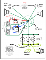
Just in case it may help in case you have a ground problem attached it is a start ground drawing that I am using in my LM3886. I have an upset of 1.9 millivolt at the speaker output with the input grounded. Compare it against your ground. Good luck
Just in case it may help in case you have a ground problem attached it is a start ground drawing that I am using in my LM3886. I have an upset of 1.9 millivolt at the speaker output with the input grounded. Compare it against your ground. Good luck
Attachments
this grounding scheme is slightly modified from the one you've shown. It can keep some ripple out of the ground system. YMMV, as depending on the details of your star arrangement, you may have avoided the effect of the narrow cap charging pulses on your ground system.
Essentially this picture is shown in Doug Self's book Audio Power Amp Design, 6th edition, Figure 11.4, page 291.
Essentially this picture is shown in Doug Self's book Audio Power Amp Design, 6th edition, Figure 11.4, page 291.
Attachments
post5 shows an improvement that is very sensible.
Breaking the green wires to the Main Audio Ground (Star Ground) and replacing them with rectifier to smoothing capacitor wiring.
This can be further improved by breaking the red link and instead taking the +ve Zero Volts wire to the -ve Zero Volts cap terminal. Just ONE grounding wire reference from the PSU to the Main Audio Ground.
answer to DJOFFE : no noise if I unplug the rca input.
Anybody have another tips because I'm in star ground and I have this noise in my amp
I view many project with filter added before star ground and other with 0.5 ohm resistor !?
I need more help!")
thanks!
dvrlfg
Anybody have another tips because I'm in star ground and I have this noise in my amp
I view many project with filter added before star ground and other with 0.5 ohm resistor !?
I need more help!
thanks!
dvrlfg
Last edited:
Okay I look on your shematic diagram of star ground but I read on many post in forum to isolate the signal ground of the power supply ground, this is what I do.
My power supply ground is independent of audio board (like real gaincard amplifier) . this is bad idea or good?
thanks
dvrlfg
by the way anybody have I picture of your gainclone project star ground ? (because I'm a idiot I need to view!)
My power supply ground is independent of audio board (like real gaincard amplifier) . this is bad idea or good?
thanks
dvrlfg
by the way anybody have I picture of your gainclone project star ground ? (because I'm a idiot I need to view!)
Last edited:
By power supply ground you mean the earth ground (that comes next to 230/110V)?
http://mark.rehorst.com/LM3886_amp/interior_of_finished_amp.jpgHere is a pic, but he also connected the earth to the ground.
I also didn't connect earth to the gorund and only get a slight humm at full power if I put my ear on the speaker.
where is the Line in ground connected together?
Maybe it creates some kind of strange loop some how. I would test to disconnect one sides earth.
Last edited:
Sorry but I need real answer!
The original gaincard is very basic 9 parts amplifier with separated power supply (I copy on that to build my gainclone) and this amp doesn't have any ground and no complex circuits and the result is the silence why the copy is so noisy!?
thanks for you help !
dvrlfg
The original gaincard is very basic 9 parts amplifier with separated power supply (I copy on that to build my gainclone) and this amp doesn't have any ground and no complex circuits and the result is the silence
why the copy is so noisy!?thanks for you help !
dvrlfg
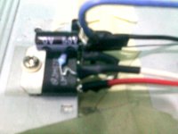
it was discovered by pulling on the wires, giving short
strait shots, and it got loose at the second i think it was
holding by the thermofit
now it hums a bit, but it is outside by the fan,tv,solder iron etc.
and i have it with input signal thru bare wires, no shield...
so, its very quiet!
strait shots, and it got loose at the second i think it was
holding by the thermofit
now it hums a bit, but it is outside by the fan,tv,solder iron etc.
and i have it with input signal thru bare wires, no shield...
so, its very quiet!
Attachments
Last edited:
The diagram in post 5 is pretty good, except that the signal input ground conductors should very-closely follow the signal input conductors (tightly twisted with them, and then as ground plane for, or as traces that stay extremely close to, the signal traces) ALL THE WAY TO the amplifiers' input resistors' ground ends, before they go to the star ground. (And they should generally be isolated from, and go to the star ground separately from, the audio board's power ground, to prevent hum, crosstalk, and noise from "ground bounce" voltages summing with the input signal.)
Otherwise, the input ground conductors will have "enclosed loop area" between them and the input signal conductors, which will make antennas for receiving hum. (See Faraday's Law: Time-varying magnetic fields in the air will induce time-varying currents in every closed loop, in proportion to the geometric area enclosed by the loop. And vice-versa.)
If someone then also did not tightly twist all of their transformer (and other) wire pairs, those would be antennas for transmitting hum. That could greatly increase the potential for hum getting into the amplifier inputs.
Usually, if the input signal/ground loop area is a problem, there will be much less hum (or no hum) until the inputs are connected (or shorted), which closes the loop and forms the "antenna".
It's also possible to get hum if one of the input grounds has a bad connection, because that forces the ground current to flow in a much larger loop, by some other route. The current WILL get back to the source's output ground connector, SOMEHOW.
It's also possible to get hum if the input RCA connector's ground is shorted to the chassis, since then the ground current would detour through the chassis, and since it would then not stay right against the signal conductor, an antenna would be formed.
In the case being discussed here, since the hum is so loud, if a loop antenna is causing it then either the loop is very large or the input signal or ground conductor is very close to a transformer or rectifier pair. Best guess is probably a bad input ground connection that is forcing the ground current to flow by some much longer route, far from the signal conductor. Probably an open signal input ground somewhere between source and amplifier input resistor but could also be an input ground shorted to chassis.
Last edited:
Pardon me, but it only takes a moment to look at the PCB image linked in post 1 and see there's a ground loop formed through one amplifier's input, its ground connection to the supply board, and back through other amp board's supply connection. Even if the remote ends of both RCAs terminate at the same point and are held at the same voltage as the supply board ground current will still flow in the loop due to any mismatch in the cabling and connector ground conductor impedances or any difference in the amplifiers' current consumption. This is assuming the input grounds are soldered in as shown on the boards, which seems likely. It's an in circuit, DC coupled crosstalk problem so twisting won't help.
If so, this is a classic problem with failure to follow the best practice of connecting incoming signal ground to the chassis. The diagram in post 5 also makes this mistake. Since the inputs are unbalanced there's 0dB CMRR so all bounce in the ground due to the loop appears on the amplifier input. Since the LM3886 has a minimum gain of 10 for stability it will amplify the ground bounce, including that generated by its own current draw, by at least 20dB. If you figure typical wiring and connectors and few amps of current being pulled by one amp channel it's not hard to get 100+mV of bounce; 1+V into a speaker is pretty loud.
Avoiding contact mating resistance (by soldering power cables directly to the boards rather than using connectors) and applying parallel earth conductors as described in the above link can mitigate the problem. It's better to implement a more robust ground topology (see link, again), use balanced interconnects to get at least some CMRR, and reduce the power amp gain to only what's needed as the reality of circuit implementations like this is usually mV of ground bounce happen. Unfortunately that's mostly not an option without different amp and supply boards---these amp boards are pretty thorough about shorting input and output ground so implementing pseduodifferential requires lifting pins. An easier band aid is to just to use signal transformers to allow each amp channel's input to float with its local ground voltage. There are better ways---the THAT 1200, in particular, outperforms probably the majority of signal trafos---but different boards are again wanted.
Last edited:
- Status
- This old topic is closed. If you want to reopen this topic, contact a moderator using the "Report Post" button.
- Home
- Amplifiers
- Chip Amps
- gainclone LM3886 noise