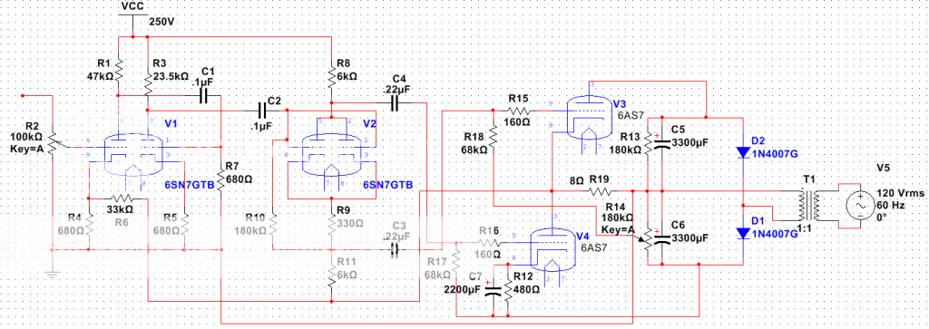
Hello. I'm a broke college EE student. I've been into HiFi tube audio since I got a pair of Heathkit A-7 monoblocks for free, and recently I've gotten into Quadraphonic audio. I soon got sick of the crummy SS amp I was using for quad, and after shopping for two more A-7s, realized the only way I could afford to have a quad tube amp is to build one. After some reading and thought I settled on a reverse connected Futterman OTL topology as it seems to be the best way to make an amp as good or better than my A-7s with minimal cost for any parts that the parts stashes of my tube radio and TV restoration hobby lack. I started out with some TV sweep tubes for outputs, and looked for a decent simple driver circuit(why reinvent the wheel when there are so many good designs that exist). I found the one in the link below, and built a modified version of it as a mono test channel which matches the power of my A-7s(with an 8 Ohm load). http://www.audiodesignguide.com/my/OTL_version_82_cheap.gif I then found a local source for cheap 6AS7 tubes and since they preformed as well as the TV tubes(I can get the power I want into my 8 Ohm speakers with only one 6AS7 per channel), that combined with some mounting advantages convinced me to change my design over to them. I presently have a two channel prototype built and after putting some time on it there are some aspects of the behavior that lead me to question the design I'm using(the schematic is below this paragraph). What bothers me the most is that, despite not redplateing, some of my 6AS7s have lost emission and have become useless. My cathode resistors are made up of three 2W or more resistors put in parallel to achieve the right resistance(so it is possible they are drifting in operation). I also find it odd that I can change the load resistor(used in place of a speaker during some tests) from 4 Ohms to over 16 Ohms and not get noticeable change in maximum undistorted signal voltage across the load...Meaning lower impedance speakers are actually getting more power delivered to them which seems counter intuitive to me. Lastly putting two 6AS7 tubes in push-pull-parallel does not yield a noticeable increase in power which does not make sense to me.
 What are your opinions of the design? And do you think it is bad components or a bad design causing it to eat tubes?
 What are your opinions of the design? And do you think it is bad components or a bad design causing it to eat tubes?
Need new schemo. If that's what you built, it shouldn't work at all. The negative rail is connected to the plates, and the positive to the cathodes. You have zero bias on the upper triode(s). Half wave rectifiers are horrible, and the DC magnetization should put the PTX into core saturation.
You can overcome Miles' correct objection to DC magnetization by using the diode/cap. stack arrangement in the B+ PSU of "El Cheapo". EC uses a doubler configuration, but PSUs are inherently differential. We arbitrarily ground some point. For a bipolar PSU, ground the junction of the 2 caps. in the stack.
BTW, use UF4007s, instead of 1N4007s, and greatly reduce the amount of switching noise generated.
BTW, use UF4007s, instead of 1N4007s, and greatly reduce the amount of switching noise generated.
Attachments
Hmm--Looks like you drew your diodes in the PSU the wrong way round....
As Miles says--Half-wave is hideous, it will cause loads of hum and stress the caps and Tx in the PSU stages....
Easy to sort--Just use a full-wave bridge and alter the scheme accordingly...
There may be other issues with it--but those are the glaring obvious ones...
As Miles says--Half-wave is hideous, it will cause loads of hum and stress the caps and Tx in the PSU stages....
Easy to sort--Just use a full-wave bridge and alter the scheme accordingly...
There may be other issues with it--but those are the glaring obvious ones...
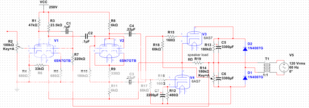
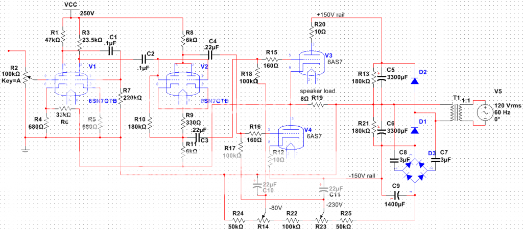
I'm glad I can wire better than I can draw a schematic. Yeesh! Here is what I actually wired minus the brain farts of the previous drawing.
 I'm not noticing hum or switching noise in use, but I was planing to switch to tube rectification when I get around to building a proper PS chassis(the diodes were a temporary measure to build it faster). @Eli my PS is essentially the EC PS with the cap junction grounded as you describe except for the elimination of the choke and what is beyond it. This doubler configuration was virtually universal in 'hot chassis' power-transformer-less tube era TVs here in the USA(I've even seen it in sets that do have a power transformer) and It does preform decently in all applications I've seen. I don't want to use any power transformers other than the spare 1940's tube radio power transformers I have and my spare bench mains isolation transformer(I also want to avoid using chokes). I only have an isolation transformer in the output PS circuit to prevent having a hot chassis in my amp. The mains here are ~120V AC and I don't have any step up transformers that are rated for the hefty current that I gather the output stage of an OTL needs so I'm kind of stuck with a doubler, or reduced rail voltage(I'm getting 155V on the rails with my current scheme).
 I'm not noticing hum or switching noise in use, but I was planing to switch to tube rectification when I get around to building a proper PS chassis(the diodes were a temporary measure to build it faster). @Eli my PS is essentially the EC PS with the cap junction grounded as you describe except for the elimination of the choke and what is beyond it. This doubler configuration was virtually universal in 'hot chassis' power-transformer-less tube era TVs here in the USA(I've even seen it in sets that do have a power transformer) and It does preform decently in all applications I've seen. I don't want to use any power transformers other than the spare 1940's tube radio power transformers I have and my spare bench mains isolation transformer(I also want to avoid using chokes). I only have an isolation transformer in the output PS circuit to prevent having a hot chassis in my amp. The mains here are ~120V AC and I don't have any step up transformers that are rated for the hefty current that I gather the output stage of an OTL needs so I'm kind of stuck with a doubler, or reduced rail voltage(I'm getting 155V on the rails with my current scheme).
The "full wave" doubler is found in a number of revered vintage amps. The H/K Cit. 2, Marantz 8B, and some McIntosh models use it. Avery Fisher was keen on the doubler too.
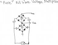
A genuine full wave multiplier is available. However, as is always the case, TANSTAAFL applies. The "arm" caps. should be AC motor run. Electrolytic caps. are fine, in the central "spine". If you have an obscenely large isolation trafo, you could use the true full wave multiplier to build a "balls to the wall" bipolar PSU.
BTW, the strain on the "spine" caps. and the diodes is uniform. The strain on the arm caps. increases with the number of stages.
Attachments

Um... isn't that what the OP has already?You can overcome Miles' correct objection to DC magnetization by using the diode/cap. stack arrangement in the B+ PSU of "El Cheapo".
Well,it will work just fine...for a,more or less,short time.
The problem is the very low load,giving an allmost vertical loadline.
Without signal you have (aprox.)Ia=120mA Vg=-55V and Pa round 17W,somewhat to much not catastrophic.
To drive the tube to the max. you apply +-50V.Now 50V up to 55+50V neg grid gives Ia ~0mA but with 50V down you get -Vg=5V.The corresponding Ia is way out of the curves.Assume 8mA/V -> 8x50+120=520mA.Since the transconductance goes up with Ia it's even worse.(Not) the way to (mis)tread that tube!
Mona
I'm glad I can wire better than I can draw a schematic. Yeesh! Here is what I actually wired minus the brain farts of the previous drawing.An externally hosted image should be here but it was not working when we last tested it.I'm not noticing hum or switching noise in use, but I was planing to switch to tube rectification when I get around to building a proper PS chassis(the diodes were a temporary measure to build it faster). @Eli my PS is essentially the EC PS with the cap junction grounded as you describe except for the elimination of the choke and what is beyond it. This doubler configuration was virtually universal in 'hot chassis' power-transformer-less tube era TVs here in the USA(I've even seen it in sets that do have a power transformer) and It does preform decently in all applications I've seen. I don't want to use any power transformers other than the spare 1940's tube radio power transformers I have and my spare bench mains isolation transformer(I also want to avoid using chokes). I only have an isolation transformer in the output PS circuit to prevent having a hot chassis in my amp. The mains here are ~120V AC and I don't have any step up transformers that are rated for the hefty current that I gather the output stage of an OTL needs so I'm kind of stuck with a doubler, or reduced rail voltage(I'm getting 155V on the rails with my current scheme).
Your output stage looks a bit unbalanced, with the way the bias is done. I recently built an OTL using 6082 tubes, which are essentially the same as 6AS7s except for the heater voltage. I based my design on a small variation of the 1950s schematic of Dickie and Makovski, which can be found by web searches. It is not permitted to talk about the original schematic on this forum, because it was directly mains connected. But the idea can be used, with power supply transformers, to conform with permitted standards for discussion.
As a small comment, I think that although the half-wave rectification you are using may not be ideal, it actually would not put a big DC bias on the power transformer, because one rectifier is taking the positive half cycles and another is taking the negative half cycles.
Chris
As a small comment, I think that although the half-wave rectification you are using may not be ideal, it actually would not put a big DC bias on the power transformer, because one rectifier is taking the positive half cycles and another is taking the negative half cycles.
That's correct. Except for minor imbalance effects, there is no "standing" DC on the power trafo secondary.
 It's exactly the same situation as that found in "full wave" doubler supplies.
I'm having trouble with graphics, today.
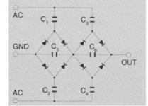
 Let's try 2 versions of the true full wave multiplier. The "purty" original was taken from VMI's site.
Attachments
The "full wave" doubler is found in a number of revered vintage amps. The H/K Cit. 2, Marantz 8B, and some McIntosh models use it. Avery Fisher was keen on the doubler too.
A genuine full wave multiplier is available. However, as is always the case, TANSTAAFL applies. The "arm" caps. should be AC motor run. Electrolytic caps. are fine, in the central "spine". If you have an obscenely large isolation trafo, you could use the true full wave multiplier to build a "balls to the wall" bipolar PSU.
BTW, the strain on the "spine" caps. and the diodes is uniform. The strain on the arm caps. increases with the number of stages.
That circuit is interesting and I do have two pairs of matched AC motor caps( a pair of 88uF and a pair of 160uF) laying around... When you say 'the strain on the arm caps increases with the number of stages' do you mean number of output stages connected to the PS or the number of floating bridges stacked output to output? Correct me if I'm wrong, but this circuit eliminates the need to use an isolation transformer to prevent the chassis from being electrically hot right?
@Ketje: So basically what your saying is that with no signal I'm biasing the cathode current near the max speck for the tube and when the signal raises the grid voltage it causes the cathode current to go way over the max current speck essentially stripping the cathode, right?
So basically I need to reduce the quiescent current (lowering the power I can get form the single 6AS7 output tube configuration I have), and put more output tubes in parallel so the output power remains unchanged, but the power through a given output tube is less than what it presently is. Anyone think that I should ditch the automatic cathode biasing scheme I have for the lower output tube and build a negative grid bias supply for it? BTW to those who are managing to get spaces between their paragraphs: How do you get that to work? I keep hitting enter twice at the end of my paragraphs and when it gets posted those spaces magically disappear...It is really starting to get on my nerves that this forum won't let me put spaces between my paragraphs.
That circuit is interesting and I do have two pairs of matched AC motor caps( a pair of 88uF and a pair of 160uF) laying around... When you say 'the strain on the arm caps increases with the number of stages' do you mean number of output stages connected to the PS or the number of floating bridges stacked output to output?
It's the number of stacked, floating, bridges.
Never, ever, build anything without a transformer to isolate people from the AC mains!!
one word.
Bias
switch bias from cathode bias to grid bias as these tubes (6as7) work better in grid bias with a little degeneration.
rework power supply with doubling the negative rail.
then voltage divide the negative doubled rail to get the top bias (dc offset) and lower bias ( stage bias)
remove the 480 ohm resistor as well as the bypass cap. instead, use 47 thru 200 ohm resistor on the lower cathode and one on the upper plate.
Thanks for the advice I'll give that a try next time I get a chance to work on it.
@Eli: Thanks for the advice, and no need to blow a fuse. As I understand the term hot chassis it reflects a DC path between the AC mains and the chassis so seeing that the circuit had no DC path between the mains and chassis(because of the arm caps) I was wondering if simply connecting the chassis to ground on a grounded 3 prong outlet and not using an isoltion transformer would work...From your response I guess my line of thinking must have been wrong. I'm not some greenhorn without knowledge or respect for electricity. I am 21 years old, I have been collecting antique tube radios(around half of which are factory designed hot chassis 'All American Five' sets) since I was 5 years old, and I have been repairing them since I was 10 years old...I have owned and been around well over 150 pieces vintage gear that were made at a time hot chassis were UL approved in consumer electronics(approximately the 1930's thru the 70's) for basically 3/4 of my life and I have a healthy respect for hot chassis electronics as well as the reasons why no one makes it any more, and know the proper safety procedures to use when repairing such vintage gear(otherwise I would not own one mains isolation transformer let alone have a spare). I don't want to make a hot chassis amp as I know what would happen if I were to interface it to my solid state signal sources(cue the 'magic smoke' sound effect), I just like the idea of keeping the design simple and not using my backup transformer if it is not needed for safety reasons.
@Eli: Thanks for the advice, and no need to blow a fuse. As I understand the term hot chassis it reflects a DC path between the AC mains and the chassis so seeing that the circuit had no DC path between the mains and chassis(because of the arm caps) I was wondering if simply connecting the chassis to ground on a grounded 3 prong outlet and not using an isoltion transformer would work...From your response I guess my line of thinking must have been wrong. I'm not some greenhorn without knowledge or respect for electricity. I am 21 years old, I have been collecting antique tube radios(around half of which are factory designed hot chassis 'All American Five' sets) since I was 5 years old, and I have been repairing them since I was 10 years old...I have owned and been around well over 150 pieces vintage gear that were made at a time hot chassis were UL approved in consumer electronics(approximately the 1930's thru the 70's) for basically 3/4 of my life and I have a healthy respect for hot chassis electronics as well as the reasons why no one makes it any more, and know the proper safety procedures to use when repairing such vintage gear(otherwise I would not own one mains isolation transformer let alone have a spare). I don't want to make a hot chassis amp as I know what would happen if I were to interface it to my solid state signal sources(cue the 'magic smoke' sound effect), I just like the idea of keeping the design simple and not using my backup transformer if it is not needed for safety reasons.
Thanks for the advice I'll give that a try next time I get a chance to work on it.
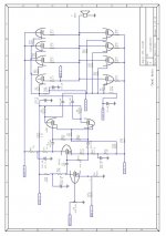
This schematic, by Christian Lopes, is what I based my OTL using 6080 tubes on. It appeared on one of the forums a couple of years ago. It's fixed bias, and just has 2.7 ohm resistors in series with the cathodes of each triode, to help with balancing between them.
Chris
Attachments
The problem with auto(cathode-resistance)bias is that it depents on the currentcosuption of the outputstage.That's fine for classA amps but this is allmost classB where the current goes up with the outputpower.The more power the more neg.bias-voltage giving a lower quiecent current.The upper tube having a fix -Vg ,the cathode goes down to adjust for the lower current,there goes your zero out-voltage= DC-component out.
On the other hand,fix bias.Adjust lower -Vg for the right current,adjust upper -Vg (existing trimpot) for zero volt out.Since the two influence eachother,repeat severel times.After that hope (an/or pray)that the tubes don't change (age) to fast.
Putting more tubes in parallel will help,but it is still much power for little result.After all 500mA peak in 8ohm's only represents 1W sine-power.You better use some EL509's.
The schematic shown by cnpope will probably work but I don't like it.
The grid of the upper and lower triodes gets the same signal-amplitude from the fasesplitter.That's not right,when the lower gets Vg then the upper needs Vg+Vout.
Now Vout<<Vg so not that dramatical but never the less...
Mona
My opinion is that the single advantage of any OTL SEPP output power stage topology is that we can optionally use bipolar supply lines with virtual ground , where chance of speaker destroying from eventually output DC offset is significantly reduced ,
but than values and quality of Elko`s from bipolar PSU determine pretty much the final sound of OTL Amp , since than OTL Amp is not anymore DC coupled to (load) speaker .
For example , bipolar PSU with virtual ground is present on Tim Mellow (SEPP) OTL Amp
.
Disadvantage of SEPP OTL circuit is must use of heavy GNFB level , and local bootstrap loop`s , which often can lead to OTL Amp oscillation , special when OTL is badly matched with low Z ( load) speaker , or SEPP OTL is done from inexperienced DIY guy`s .
That's fine for classA amps but this is allmost classB where the current goes up with the outputpower. Putting more tubes in parallel will help,but it is still much power for little result.After all 500mA peak in 8ohm's only represents 1W sine-power.You better use some EL509's.
The schematic shown by cnpope will probably work but I don't like it.
The grid of the upper and lower triodes gets the same signal-amplitude from the fasesplitter.That's not right,when the lower gets Vg then the upper needs Vg+Vout.
Now Vout<<Vg so not that dramatical but never the less...
Mona
Very interesting. I originally designed the output on my amp to be class A(I think I had read somewhere no the net that Futterman style amps had to be class A) I did not read the 125mA max values on the data sheet and since the curves went to 200mA on the data sheet I tried to design it to have a quiescent current of 100mA.
I don't think I can afford EL509's, though I may have one or two in my stocks of TV sweep tubes(I also as a general rule don't like using tubes with non-USA ID codes). I can get 6AS7GA's for 5$ a piece locally from a dealer I know so I'd like to stick with those. I don't want to put more than 50$ in to parts which I don't already have laying around in my parts bins
If I were to change tubes I think I'd go with 6JA5's I have about 6 of them laying around, and before I found a source for cheap 6AS7's I had a working prototype based on them that had the same output power I currently am getting with the flawed design I posted.
My goal is to build a 4 channel amp so I'd like to keep parallelism to a minimum(or not do it at all) so the chassis does not become excessively big.
I'm working on building the PS circuit Eli posted(Thank you Eli) I'm using 3uF AC motor caps on the arms(because the higher value ones I have tested leaky), and 1400uF lytics for the spine. I like that the lytics don't charge instantly like on my old doubler circuit(it would dim the lights on power up worse than my all tube color TV sets do), but wonder if the small motor caps will limit the current that the supply can produce too much. I plan to build at least three of these floating bridges for plus and minus output rails, and grid bias. Though I may make four so I can derive the preamp B+ supply from it...
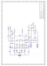
Well since the floating bridge PS circuit(as the caps I have allow me to build it) has SIGNIFICANT voltage sag under the load of the output PS rails I've decided to abandon it's use for the output rails and return to the original doubler configuration I had, but this time with a twist. I'm going to stack the floating bridge with my old doubler so that the floating bridge will give me a negative grid bias supply. How does this version of the circuit look? R14 and R23 are supposed to be 50k Ohms.

- Status
- This old topic is closed. If you want to reopen this topic, contact a moderator using the "Report Post" button.
- Home
- Amplifiers
- Tubes / Valves
- OTL design opinion