Actually, even D. Self acknowledges that it is, in fact, a TIS in his book, although he mistakenly called it a TAS in his fifth edition.
And, no, so-called no-feedback amplifiers are not the subject of this debate. You still haven't read Solomon I take it.
Yes, I have read Jim Soloman's excellent book. Indeed I've known Jim since before you were in diapers. Same goes for Willie, Barrie, Bob, Ken and many others. You can fill in the last names if you know them.
When did you ever present a paper at the ISSCC (the International Solid State Circuits Conference, in case you didn't know or never went)?
We all know that you are well-read. Unfortunately, reading does not by some magical process of osmosis impart wisdom, experience, common sense, good judgment and least of all courtesy.
Cheers,
Bob
 OT posts removed.
The simpler-is-better answer!
I was asking about his incomplete Wireless World amplifier series which is now re-printed in Jan Didden's book. (The series includes many gems including his analysis of what feedback does to distortion) It goes something like this ..
Stages with local feedback (less gain) mean previous stages have to provide more output increasing their THD etc and this is a vicious cycle. Most of the time, you are lucky to get 10dB better THD improvement with each extra stage. Bob's Chapter 3 is a good example/discussion though mainly in SPICE world. Remember, an extra small signal BJT should add at least 40dB of current gain.
I've tried in 'real life' most of the things Bob enumerates, input cascode, a good current mirror, a 2 transistor VAS, a push-pull VAS, a cascoded VAS, or an output Triple .. and yes they provide improvements. But most of the time, I've been able to use this as a target and get similar improvements with my simpler, naive circuits. eg a push-pull VAS often just highlights 'mismatched' outputs, drivers & pre-drivers as the main 2nd harmonic mechanism.
Often, simpler circuits have better overload & recovery characteristics too.
I apologise to da the Complex Amp Gurus CAGs, Bob, Harry, Edmond etc but this is a 'philosophy' rather than something to be blindly followed. I accept the CAG amps have supa performance in spite of their complexity
But there are a lot of complex amps with MUCH poorer performance than my naive circuits .. certainly those from the semantic pendantic pseuds who spurn 'real life' stuff and prefer their sims and wonky theory.
________________
An example of this 'philosophy' ..
If we take the simple amp in the above list, sorta Bob's Fig 3.2 but with a CM on the input (turning it upside down for secret reasons which I won't discuss here) and making R11+12 a single resistor ...
Converting that to 'pure Cherry' gives performance that is hard to equal without more complexity. This is completely in-line with what Cherry analyzes in Feedback, Sensitivity and Stability of Audio Power Amplifiers It's very stable, only 3 actives in the loop. Far less likely to suffer from Excess phase stuff and Cherry's VAS emitter resistor works well in theory & practice.
'Real life' THD @20kHz can get below 30ppm for a 50W version even with Jurassic devices & test gear.
What we've done is to take a heavily degenerated (by Cdom) VAS and let it run free. The output stage that was previously 'voltage' driven, ie operated as an emitter follower with loadsa local feedback, is now 'current' driven and behaves more like a 'common emitter' stage (Baxandall loved to transform the ways he looked at things.) Loadsa extra Loop Gain in both stages.
This extra Loop Gain also comes with a more 'linear' Output stage. The xover distortion of the Class B emitter follower with critical operating points ... is replaced by far lower orders due to hfe mismatch and droop. (Loadsa dodgy caveats in this statement but at the end of the day, you'll see improved THD all round, much low orders in what's left and practically no xover spikes.)
__________________
I've had some 'real life' success in extending this to an enhanced VAS but Guru's JPV & Zan show this is certainly non est tantum facile.
__________________
I was going to discuss some practical aspects of this 'philosophy' .. remember its just a way of looking at things. But don't wanna open myself to fire from da semantic pedantic pseuds.
__________________
PS I want 1ppm THD @ 20kHz like da CAGs too but want it with 'simple'.
I'm going to describe a 'philosophy' which I first heard directly from Great Guru Baxandall in the 70's when he was kind enough to indulge in copious correspondence with a young wannabe.Bob Cordell said:Making the open loop more linear will, however, often mean using more transistors, such as an input cascode, a good current mirror, a 2 transistor VAS, a push-pull VAS, a cascoded VAS, or an output Triple. While these may go against the grain of the simpler-is-better advocates, they do not usually go against amount of loop gain or safe ULGF.
I was asking about his incomplete Wireless World amplifier series which is now re-printed in Jan Didden's book. (The series includes many gems including his analysis of what feedback does to distortion) It goes something like this ..
- if you work out the Open Loop gain of a simple amp, eg 2EF, single device VAS & LTP i/p with CM, without any compensation, you'll note a huge amount of gain available even with wonky loads & Jurassic devices. If you can somehow use 90% of this gain and have a stable amp, you will have 1ppm THD to 20kHz with a very simple circuit.
- If you run a 'stage' with very high gain, its input distortion will be less as it uses a smaller part of its input 'transfer' function.
Stages with local feedback (less gain) mean previous stages have to provide more output increasing their THD etc and this is a vicious cycle. Most of the time, you are lucky to get 10dB better THD improvement with each extra stage. Bob's Chapter 3 is a good example/discussion though mainly in SPICE world. Remember, an extra small signal BJT should add at least 40dB of current gain.
I've tried in 'real life' most of the things Bob enumerates, input cascode, a good current mirror, a 2 transistor VAS, a push-pull VAS, a cascoded VAS, or an output Triple .. and yes they provide improvements. But most of the time, I've been able to use this as a target and get similar improvements with my simpler, naive circuits. eg a push-pull VAS often just highlights 'mismatched' outputs, drivers & pre-drivers as the main 2nd harmonic mechanism.
Often, simpler circuits have better overload & recovery characteristics too.
I apologise to da the Complex Amp Gurus CAGs, Bob, Harry, Edmond etc but this is a 'philosophy' rather than something to be blindly followed. I accept the CAG amps have supa performance in spite of their complexity
But there are a lot of complex amps with MUCH poorer performance than my naive circuits .. certainly those from the semantic pendantic pseuds who spurn 'real life' stuff and prefer their sims and wonky theory.
________________
An example of this 'philosophy' ..
If we take the simple amp in the above list, sorta Bob's Fig 3.2 but with a CM on the input (turning it upside down for secret reasons which I won't discuss here) and making R11+12 a single resistor ...
Converting that to 'pure Cherry' gives performance that is hard to equal without more complexity. This is completely in-line with what Cherry analyzes in Feedback, Sensitivity and Stability of Audio Power Amplifiers It's very stable, only 3 actives in the loop. Far less likely to suffer from Excess phase stuff and Cherry's VAS emitter resistor works well in theory & practice.
'Real life' THD @20kHz can get below 30ppm for a 50W version even with Jurassic devices & test gear.
What we've done is to take a heavily degenerated (by Cdom) VAS and let it run free. The output stage that was previously 'voltage' driven, ie operated as an emitter follower with loadsa local feedback, is now 'current' driven and behaves more like a 'common emitter' stage (Baxandall loved to transform the ways he looked at things.) Loadsa extra Loop Gain in both stages.
This extra Loop Gain also comes with a more 'linear' Output stage. The xover distortion of the Class B emitter follower with critical operating points ... is replaced by far lower orders due to hfe mismatch and droop. (Loadsa dodgy caveats in this statement but at the end of the day, you'll see improved THD all round, much low orders in what's left and practically no xover spikes.)
__________________
I've had some 'real life' success in extending this to an enhanced VAS but Guru's JPV & Zan show this is certainly non est tantum facile.
__________________
I was going to discuss some practical aspects of this 'philosophy' .. remember its just a way of looking at things. But don't wanna open myself to fire from da semantic pedantic pseuds.
__________________
PS I want 1ppm THD @ 20kHz like da CAGs too but want it with 'simple'.
It is difficult to let understand colours to somebody watching a black and white with TV .
There is a joke which says that a B&W TV is in colours if you consider black and white as being colours.
I'm going to describe a 'philosophy' which I first heard directly from Great Guru Baxandall in the 70's when he was kind enough to indulge in copious correspondence with a young wannabe.
I was asking about his incomplete Wireless World amplifier series which is now re-printed in Jan Didden's book. (The series includes many gems including his analysis of what feedback does to distortion) It goes something like this ..
But non est tantum facile. Most compensation schemes throw away most of this huge available gain and you need extra stages & complexity to get 1ppm THD.
- if you work out the Open Loop gain of a simple amp, eg 2EF, single device VAS & LTP i/p with CM, without any compensation, you'll note a huge amount of gain available even with wonky loads & Jurassic devices. If you can somehow use 90% of this gain and have a stable amp, you will have 1ppm THD to 20kHz with a very simple circuit.
- If you run a 'stage' with very high gain, its input distortion will be less as it uses a smaller part of its input 'transfer' function.
Stages with local feedback (less gain) mean previous stages have to provide more output increasing their THD etc and this is a vicious cycle. Most of the time, you are lucky to get 10dB better THD improvement with each extra stage. Bob's Chapter 3 is a good example/discussion though mainly in SPICE world. Remember, an extra small signal BJT should add at least 40dB of current gain.
I've tried in 'real life' most of the things Bob enumerates, input cascode, a good current mirror, a 2 transistor VAS, a push-pull VAS, a cascoded VAS, or an output Triple .. and yes they provide improvements. But most of the time, I've been able to use this as a target and get similar improvements with my simpler, naive circuits. eg a push-pull VAS often just highlights 'mismatched' outputs, drivers & pre-drivers as the main 2nd harmonic mechanism.
Often, simpler circuits have better overload & recovery characteristics too.
I apologise to da the Complex Amp Gurus CAGs, Bob, Harry, Edmond etc but this is a 'philosophy' rather than something to be blindly followed. I accept the CAG amps have supa performance in spite of their complexity
But there are a lot of complex amps with MUCH poorer performance than my naive circuits .. certainly those from the semantic pendantic pseuds who spurn 'real life' stuff and prefer their sims and wonky theory.
________________
An example of this 'philosophy' ..
If we take the simple amp in the above list, sorta Bob's Fig 3.2 but with a CM on the input (turning it upside down for secret reasons which I won't discuss here) and making R11+12 a single resistor ...
Converting that to 'pure Cherry' gives performance that is hard to equal without more complexity. This is completely in-line with what Cherry analyzes in Feedback, Sensitivity and Stability of Audio Power Amplifiers It's very stable, only 3 actives in the loop. Far less likely to suffer from Excess phase stuff and Cherry's VAS emitter resistor works well in theory & practice.
'Real life' THD @20kHz can get below 30ppm for a 50W version even with Jurassic devices & test gear.
What we've done is to take a heavily degenerated (by Cdom) VAS and let it run free. The output stage that was previously 'voltage' driven, ie operated as an emitter follower with loadsa local feedback, is now 'current' driven and behaves more like a 'common emitter' stage (Baxandall loved to transform the ways he looked at things.) Loadsa extra Loop Gain in both stages.
This extra Loop Gain also comes with a more 'linear' Output stage. The xover distortion of the Class B emitter follower with critical operating points ... is replaced by far lower orders due to hfe mismatch and droop. (Loadsa dodgy caveats in this statement but at the end of the day, you'll see improved THD all round, much low orders in what's left and practically no xover spikes.)
__________________
I've had some 'real life' success in extending this to an enhanced VAS but Guru's JPV & Zan show this is certainly non est tantum facile.
__________________
I was going to discuss some practical aspects of this 'philosophy' .. remember its just a way of looking at things. But don't wanna open myself to fire from da semantic pedantic pseuds.
__________________
PS I want 1ppm THD @ 20kHz like da CAGs too but want it with 'simple'.
Pretty much sums up my experience and practice with amplifier circuits. And, I (and some others) caught onto this around the same time as Baxendal. We all came to the same point via our individual means. Which is as it should be for finding the 'best'.
Thx-RNMarsh
Last edited:
RNMarsh,
As in all engineering I have been involved with the simplest and most elegant solution is most often the best solution. Adding elements should only be done when necessary, not to add complexity for complexity state. Sometimes we have no choice, we have to add an element to overcome a problem or situation, but this should be the last resort. I know this says nothing about an electrical circuit, but I think it works the same in these instances.
ps. The principal that we learn is the Kiss principal, keep it simple stupid.
There's a couple which are close to Jurassic 'real life' amps in my http://www.diyaudio.com/forums/solid-state/235188-tpc-vs-tmc-vs-pure-cherry.html thread.I like this philosophy too. Care to share one of your designs?
I'll add to KISS, something that Scott Wurcer calls Muntzing. After you get your circuit/device etc to achieve your target, 1ppm THD @ 20kHz or whatever, whether 'real life' or sim, you systematically remove each extra dodge you put in to achieve this. Now you find out which fancy feature is really useful and which ones are icing.
Of course, if you do this in 'real life', this is affected by your tools. Because I could only measure to about 30ppm in da old days, I would Muntz stuff which showed no difference with the THD meter bottoming at 30ppm. Mea maxima culpa.
But other stuff like overload & recovery, stability (& THD) on wonky loads etc could still be done formally. It's likely this stuff that so few people do, (Bob is a shining exception) may be the real reason for the difference in sound of amps.
In da 21st century, when my livelihood doesn't rely on design decisions, chasing 1ppm @ 20kHz in SPICE world is fun .. provided you don't lose track of the other stuff that amps should do (or not do) too.
Thanks for that term, Richard, it perfectly encapsulates the same process that needs to be followed with general system tweaking - once the sound is working at a satisfactory subjective level then you remove each weird and wonderful 'mod', one at a time, in order of the most 'extreme' one first, and see what happens ...
It removes input stage DC offset; since the gate voltage is higher than the "normal" two (or three) transistor VAS; this allows larger mirror Rs for lower noise and a Wilson mirror for accuracy; less tranies in the signal path; high output Z; and the Source R manages total available I_Out. And... nothing is free.
Last edited:
JLH and others use mosFET VAS.
I think John Curl's JC1 uses a MOSFET VAS configured as a folded cascode, IIRC.
Although I like MOSFETs in the output stage, I am not convinced that they bring any advantage to the VAS function.
I like amplifiers with JFETs in the IPS, BJTs in the VAS, and MOSFETs in the OPS.
Cheers,
Bob
Belaji, a good example of KISS/Muntz would be check whether your Wilson CM actually provides any real or sim advantage over the 'simple 2 transistor CM with BC550' for THD, noise or offset.Here is an idea I came up with following the KISS view (even though I haven't seen it anywhere, I doubt it's original).
You should do this in 'real life' making sure you operate both types of CM with their optimal conditions .. and certainly in SPICE.
For offset, it is likely other factors (eg input device matching) will dominate.
keantoken has done a lot of work on quasi-saturation and the correct choice of BJT for current mirrors.
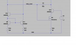
You got a good case where the TIS vs. VAS makes a difference. If you look at it as a TIS, then the transimpedance gain is exactly Beta*Rload. Moreover, if the output buffer input impedance is very large, then the gain is limited by the transistor output impedance VA/Ic (VA stands for the Early voltage). Therefore, the TIS gain is Beta*VA/Ic, independent of any emitter degeneration.
That would make sense but if VaF/Ic = Ro (output resistance)
then isnt the gain ultimately limited by Ro/(Re + 1/gm).?.
I would be most interested if you can demonstrate this.
Using your schematic as exemple , the VAS/TIS gain with
and without degeneration.
Attachments
Wahab,
do I see a steepening of the green trace from above 8Mhz?
Is this a second order effect coming in @ HF.
It seems to be suppressed until 30MHz on the red trace.
Could this complicate the steepness of the gain curve for the whole amplifier where <9dB/oct is specified for stability?
do I see a steepening of the green trace from above 8Mhz?
Is this a second order effect coming in @ HF.
It seems to be suppressed until 30MHz on the red trace.
Could this complicate the steepness of the gain curve for the whole amplifier where <9dB/oct is specified for stability?
Wahab,
do I see a steepening of the green trace from above 8Mhz?
Is this a second order effect coming in @ HF.
It seems to be suppressed until 30MHz on the red trace.
Could this complicate the steepness of the gain curve for the whole amplifier where <9dB/oct is specified for stability?
Yes , you are right in your observations.
Degeneration of the VAS not only reduce its gain
but also reduce its bandwith such that the influence
of high frequency poles is reduced accordingly but ,
as pointed by michael K , excess phase is increased
and global stability worsen somewhat , although at the
pole frequency it is improved because the inherent peak
is quite less , well , peaky.
Degeneration linearization effect falls exactly under c) (as a current-current feedback loop). If we can't agree on this elementary fact, it's indeed a waste of time to debate anything else. And please don't come up with the local vs. global NFB nonsense. Negative feedback is negative feedback, period.
This is not right.
If you add degeneration to the second stage you ll increase
the first stage output level wich will increase its distorsion ,
yet the VAS better linearity wont allow to compensate
for the first stage said harsher conditions , hence ,
feedback distribution matters as its application is not
freely transferable from a stage to the other while
keeping the same global efficency.
- Home
- Amplifiers
- Solid State
- Bob Cordell's Power amplifier book