Hi
I am not sure if this is the right place to post this, if not please move it.
I have been tinkering on an old Pioneer SA408 for some time. I have fixed many faults replaced several components.
I still have a scratchy sound on the right channel, this is a serious improvement to how I got the amp it was in a very bad state.
I don't have an oscilloscope so I have been using a set of computer speakers with built in amp to listen to the signal at various places on the board. I could not hear the scratch using this technique and later found that if I add any small resistance to the right channel output in series with the speaker the scratch disappears. Making it rather dificult to the fault with my computer speakers.
Does anyone have any idea what would cause this?
Mooly, I am not 100% sure how to measure quiescent current, I measured the current draw without load or input signal and there is none 0A.
Lanchile, I only hear the scratch with passive speakers, with my computer speakers it disappears. I assume because the input resistance of the computer speakers amp is having the same affect as a resistor in series with a passive speaker.
Lanchile, I only hear the scratch with passive speakers, with my computer speakers it disappears. I assume because the input resistance of the computer speakers amp is having the same affect as a resistor in series with a passive speaker.
You measure the (tiny) voltage across the 0.22 ohm emitter resistors in the power amp stage. I don't know what the recommended current is but anything over 10 millivolts will ensure no audible distortion is present.
Compare channels. No speakers and no signal when you measure.
Compare channels. No speakers and no signal when you measure.
Attachments
I get a 0-2mV on both Left and Right.
It seems to fluctuate ever so slightly.
is that the dc offset or the bias?
I get a 0-2mV on both Left and Right.
It seems to fluctuate ever so slightly.
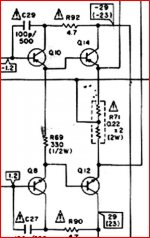
And is that across each 0.22 ohm ? You don't measure from ground to these, it is measured across them
It's no problemIf you are 100% certain the reading is zero (and as further confirmation, the output transistors will be stone cold) then there is a problem with the biasing. The circuit shows what appears to be a "fixed" select on test set up. Normally on most amps there is a preset pot.
What does the bias on the "good" channel read ? Something odd is going on here. You mentioned at the start that you replaced "many components". Have you replaced transistors and parts in the output stage ?
Normally one of the three resistors in the chain would be an adjustable preset.
Attachments
That is correct the output transistors are stone cold. I checked again and I still get 0mV across the 0.22ohm resistor legs.
Most of the components I changed where in the output stage. The output transistors where among them. I just removed components that looked damaged and replaced them with the same or components my electronics supplier assured me where equivalents.
Most of the components I changed where in the output stage. The output transistors where among them. I just removed components that looked damaged and replaced them with the same or components my electronics supplier assured me where equivalents.
That could explain things. (An adjustable pre-set is a variable resistor).
Fixed bias is super critical on the exact devices used. Best solution I think would be to replace R53 with a 1K preset and set the bias for around 15 mv (voltage across either 0.22 ohm)
You can't hope to get this correct by guessing with fixed resistors. The pot will give full control but its very important that the pot is on maximum resistance to start with. I would recommend using a bulb tester initially because one mistake will result in failure of output transistors.
I am missing something here. After replacing R53 and R54 with 1kohm pots I still get 0mV across the emitter resistor R72 and R71. There seems to be no difference no mater how much I adjust the pots.
The only time I see any DC voltage on the emitter resistors is with a speaker connected which gives 6mV on the left channel and around 1mv on the right. The right channel is the one giving distortion.
I figure I need to get the right channel to 6mV when speaker is connected?
I wish I could understand amplifier circuits.
Last edited:
- Status
- This old topic is closed. If you want to reopen this topic, contact a moderator using the "Report Post" button.
- Home
- Amplifiers
- Solid State
- Newbie vs Pioneer SA408