Help Please,
I got this bass amp at a yard sale,lol.
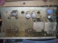
I am looking for the schematic or ANY docs on it ,it has 2 6L6's and 4 small tube's found 803 on one of them,
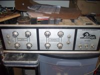
The front has 2 channels one for bass and a normal channel,and tone controls
The logo is a lion with 20Segi in it, I can't find any other numbers,yet
Thanks,
NS
I got this bass amp at a yard sale,lol.
I am looking for the schematic or ANY docs on it ,it has 2 6L6's and 4 small tube's found 803 on one of them,
The front has 2 channels one for bass and a normal channel,and tone controls
The logo is a lion with 20Segi in it, I can't find any other numbers,yet
Thanks,
NS
Wwhen I see something like this, I get out a pad and pencil, and draw my own schematic.
You should pretty much know what the circuit looks like for a pair of 6L6s. If not, draw one from say Fender Bassman and see what differences there are. They will need a phase splitter, and that will be the small tube next to the power tubes. Chances are good it is a long tail pair circuit. Again, see Fender amps.
If you are not sure what the small tubes are, look at the socket wiring. If pins 4 and 5 are wired together, and a twisted pair of wires goes socket to socket hitting pin 9 and pin 4-5 with 6.3VAC, we can assume they are 12AX7 or similar.
COnsidering it says Bass and Normal for the two channels, that sounds even more like an old Bassman, and the amp may just be a straight copy of the Fender.
hi Guys,
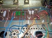
I looked and 3 of the 4 small tubes do have 4 and 5 connected,so your on track,4 of the caps will need replaced and probably some more ,one of the green resistors has been hot ,I haven't measured anything yet because I really don't know what I should have ,I'm not a tubie ,but learning fast,lol.
Here's some pics
Thanks,
NS
that valve is problly ECC803 which is a long plate 12ax7 and yes sunds like a bassman clone, any pics?
I looked and 3 of the 4 small tubes do have 4 and 5 connected,so your on track,4 of the caps will need replaced and probably some more ,one of the green resistors has been hot ,I haven't measured anything yet because I really don't know what I should have ,I'm not a tubie ,but learning fast,lol.
Here's some pics
Thanks,
NS
Attachments
Agree with Enzo and add: this is an early Korean amplifier.
It looks like a Fender clone, with *maybe* some very light tweak here and there ... or none at all.
On your "014" picture, the front right tube is the Fenderish phase inverter, complete with 470r shared cathode resistor, 1M grid resistors, 22K long tail resistor, 82K and 100K plate resistors, and so on.
Power amp sound input is through the brown ceramic capacitor partly hidden by the yellow sleeved wires, and so on.
So print, say, a Fender Bassman schematic and start comparing parts values, I bet it will be amazingly close.
Mind you, I have found at least 2 partys missing, there may be more.
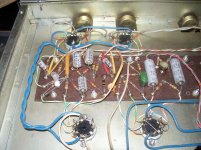
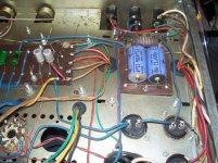
In the "015" picture, between the 3 green resistors on the left and the 2 grey capacitors+resistors on the right, I see the stumps of 2 missing parts, *maybe* another R+C pair, but, who knows?
You'll need to redraw a schematic, remember to label parts (such as R1 R2 ... C1 C2 ... V1a ... etc.) .
It looks like a Fender clone, with *maybe* some very light tweak here and there ... or none at all.
On your "014" picture, the front right tube is the Fenderish phase inverter, complete with 470r shared cathode resistor, 1M grid resistors, 22K long tail resistor, 82K and 100K plate resistors, and so on.
Power amp sound input is through the brown ceramic capacitor partly hidden by the yellow sleeved wires, and so on.
So print, say, a Fender Bassman schematic and start comparing parts values, I bet it will be amazingly close.
Mind you, I have found at least 2 partys missing, there may be more.
In the "015" picture, between the 3 green resistors on the left and the 2 grey capacitors+resistors on the right, I see the stumps of 2 missing parts, *maybe* another R+C pair, but, who knows?
You'll need to redraw a schematic, remember to label parts (such as R1 R2 ... C1 C2 ... V1a ... etc.) .
Hi,
I have looked at several bassman schematic's and think I have found one close to the number of tubes and the layout,Where might I find these tweeks you speak of,and there is 2 extra holes for 2 more 6l6 tubes can I use them also? or do I have the IRON for those,
Thanks to all who reply for info ! It's very helpful!
NS
No, I was just thinking aloud, that the amp might not be a 101% **exact** copy and some part *might* have a different value, nothing else.Hi,
I have looked at several bassman schematic's and think I have found one close to the number of tubes and the layout,Where might I find these tweeks you speak of,
Don't think so.and there is 2 extra holes for 2 more 6l6 tubes can I use them also? or do I have the IRON for those
Fact is, since unless you have a very large factory (think Fender or Peavey) usual is to order chassis made "outside", and in certain large quantities (multiples of 100), normal practice is to make a multipurpose chassis with all the holes which might be needed for various versions, in this case 50 or 100W , and stuff what's needed.
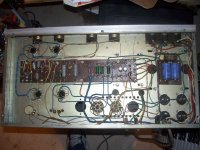
See that even the board shows unused eyelets.
But transformers even if ordered from a supplier are wound one by one and are the most expensive part of an amp, and not *really* interchangeable, so I guess you have a "50/100" chassis but "50W" iron.
But consider yourself very lucky
You have extra holes where more 6L6s might go, but it looks like the chassis is just generic, as JM said. In fact, the chassis might be repurposed from something else. This amp looks handmade to me. For example, look at picture 014, the 12AX7 sockets are pc mount types instead of solder lugs. Nothing wrong with that, but it screams basement product. Fat blue wired used over and over, while thinner various colors used elsewhere. Both radial and axial caps on the eyelet board where all axial would be expected, and on 014 near upper left socket, a couple axial caps look longer than the space between their eyelets, as if the board were made for some other part. It looks like someone knocked it together with whatever they had on hand.
hi Dave,
I have been trying to draw one,they twisted 3 or more pairs,used the same blue wires ,the hook up wire is solid copper it breaks off ez,lol.
I make pictues would you draw a schematic up ,I have tried 3 times so far getting close,I think I wil try 4 sheets of paper tomorrow maybe I won't run out of room ,they have 8 wires crossed or twisted and I draw them out it get big ,lol.
I did get a parts list together and will start looking for high voltage caps ,I a transistor guy I got most anything up to 75 volts but not much higher,
I need some 6L6's and 4 12ax7's I have the low volt caps and some of the resistors,
Would some one tell me what that black box is near the small tubes it has 2 terminals so I'm thinking a cap ,no markings at all......
Thanks
NS
A few more high res pictures and we could draw a schematic
That amp looks totally cool.
I have been trying to draw one,they twisted 3 or more pairs,used the same blue wires ,the hook up wire is solid copper it breaks off ez,lol.
I make pictues would you draw a schematic up ,I have tried 3 times so far getting close,I think I wil try 4 sheets of paper tomorrow maybe I won't run out of room ,they have 8 wires crossed or twisted and I draw them out it get big ,lol.
I did get a parts list together and will start looking for high voltage caps ,I a transistor guy I got most anything up to 75 volts but not much higher,
I need some 6L6's and 4 12ax7's I have the low volt caps and some of the resistors,
Would some one tell me what that black box is near the small tubes it has 2 terminals so I'm thinking a cap ,no markings at all......
Thanks
NS
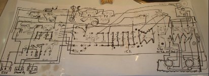
here's the schematic I have tried ,I need a tube program,I haven't used eagle in a while,might have to relearn the curve again,This is crude I will try again tomorrow,I need to clean the top side so I can trace the wires to the controls ,
Has anyone knowledge of a fender bassman with vol,treble,middle,and bass controls,I haven't found a direct clone yet,and one might not exist anyway,
I found this written on the chassis A.2.498 and then a date I believe 12-29-77 would that be a possible schematic revision,I have Google it and look at lots of schematics ,but still searching!
Nighters,
NS
Attachments
Last edited:
hi ArcticBreaze,
Thanks for the help !
NS
I cleaned the other tubes up and one is a 12ax7 and others appear to be 6021 so there all the same,I am going to clean it up tomorrow and so I can trace the wires out to the front pots,then hopefuly make a good schematic and get 'er going,lolthat valve is probably ECC803 which is a long plate 12ax7 and yes sounds like a bassman clone, any pics?
Thanks for the help !
NS
Last edited:
That black box looks like it's a choke. It appears to be between two stages of the power supply which is typical in tube amps to isolate the stages and give a small voltage drop.
Are you using a continuity tester (or ohm meter) to check the routing of wires that are bundled together? I'd offer to help, but unfortunately I don't have time, and without being able to physically check the connections I'd be just guessing on a few points.
If you're looking for a free schematic program, I've been using TinyCAD. It has some tubes already in its library, and is fairly easy to use.
Fender Bassman schematics can be found all over the internet. images.google.com search for Fender Bassman Schematic
That black box looks like it's a choke. It appears to be between two stages of the power supply which is typical in tube amps to isolate the stages and give a small voltage drop.
Are you using a continuity tester (or ohm meter) to check the routing of wires that are bundled together? I'd offer to help, but unfortunately I don't have time, and without being able to physically check the connections I'd be just guessing on a few points.
If you're looking for a free schematic program, I've been using TinyCAD. It has some tubes already in its library, and is fairly easy to use.
Hi doozerdave,
I have been pulling the bundles apart to trace them down,I ordered new tubes ,the ones in it are very old ,I'll try tinyCAD, and check that black box too!
I have looked at Fender bassman sch,but not found a exact match,some are close,but the MIDDLE tone knob I haven't found on a schematic yet,but maybe is ok as is, I plan to replace all caps and that one resistor and check the rest and give it a go and see if it works correctly,
Thanks for the info,and your time,
NS

McDonald's offers every month a "new revolutionary" Burger with a new fancy name and some toys but *all* 8942 of them are some combination or bun/patty/cheese/lettuce/tomato/special sauce, only 6 ingredients.I have looked at Fender bassman sch,but not found a exact match,some are close,but the MIDDLE tone knob I haven't found on a schematic yet,
Same with Fender: they made hundreds of models based on 1 gain stage, 2 or 3 tone controls, 2 phase inverters, 3 or 4 power amps.
The "middle" control you don't find in "Bassman" labelled schematics is the one used in guitar amps.
Same values and EQ as the other one, only they replaced the fixed 6K8 resistor with a 10 K pot.
I'm sure you have that:

hi Guys,
Well I guess I will test them and post there maker also,I got tinycad also ,on the curve now......
Thanks,
NS
If those "very old" tubes still work they could be very nice, and valuable, depending on the brand.
Well I guess I will test them and post there maker also,I got tinycad also ,on the curve now......
Thanks,
NS
hi JMFarley,
A question,any problems using film caps for the electrolytic s in those circuits,I have them already in Film wima and green mylars,
Thanks,
NS
I am a newbie on tubes,I got my education at a tech school and learned tubes and transistors a long time ago.......So I am relearning tubes now, so thanks for the help you are sharing with me ,I have that circuit in this amp,McDonald's offers every month a "new revolutionary" Burger with a new fancy name and some toys but *all* 8942 of them are some combination or bun/patty/cheese/lettuce/tomato/special sauce, only 6 ingredients.
Same with Fender: they made hundreds of models based on 1 gain stage, 2 or 3 tone controls, 2 phase inverters, 3 or 4 power amps.
The "middle" control you don't find in "Bassman" labelled schematics is the one used in guitar amps.
Same values and EQ as the other one, only they replaced the fixed 6K8 resistor with a 10 K pot.
I'm sure you have that:
A question,any problems using film caps for the electrolytic s in those circuits,I have them already in Film wima and green mylars,
Thanks,
NS
- Status
- This old topic is closed. If you want to reopen this topic, contact a moderator using the "Report Post" button.
- Home
- Live Sound
- Instruments and Amps
- 20Segi tube amp