Why does the fun always start just after I have gone to bed?
That Army report is amusing - it looks like playtime at the Army labs. No serious force measurement, so no plot of force vs. voltage or current.
Three questions (one from Newton, one from Maxwell, the last from Kirchoff):
1. if there is a force, where is the reaction?
2. if there is voltage, with respect to what?
3. if there is a current, where is the loop?
The answers to any of these questions would seem to suggest that this, even if a real effect, will never be used for a free-moving vehicle (unless it trails a cable along the ground). The Army will have to stick with its alien technology.
If you actually saw a demo you would really laugh, 50KV at enough micro-amps to be Watts of power to make a few milli-grams of foil float. Where does the current/power go, how about about corona discharge, heated air and any number of things that would create enough laminar flow.
If you actually saw a demo you would really laugh, 50KV at enough micro-amps to be Watts of power to make a few milli-grams of foil float. Where does the current/power go, how about about corona discharge, heated air and any number of things that would create enough laminar flow.
Yes they are fun.
The issue got funding when around the 50's they noted unexplained effects from high voltage capacitor stacks. I though that was where SY was going when he asked about weight rather than mass. (Although SY as a chemist certainly knows the difference.)
The pendulum when very accurately measured slows down when charged.
The "miracle capacitors" weigh less and under some conditions lift off. The report asked for funding to see if the fluid effects were responsible. I think they actually got it and made a few flyers. Of course they aren't very useful in real weather, but still very cute! if anybody wants to make their own you need a flyback power supply from an old crt display.
As to the question of pulling the plates apart to 12" the really nice corona glow is when you let them slowly come back to 1".
So unfortunately we will still have to wait for our flying cars.
")
ES
Ah yes it's there, J. Naudin electrogravidics and other assorted garbage physics (he once suggested making a three foot cube vacuum chamber out of 1/4" plexi-glass). Several universities have shown that this effect does NOT work in a vacuum, I even sent the links to a professor in Canada frustrated by this nonsense.
Not the fellow I was thinking of. If I have time I'll try to find a cite.
Is this MIT'er getting angry about the physics taught at a superb liberal arts institution down the street?
Now a three foot cube of 1/4" plexi-glass being pumped down is a video I'd like to see!
If you actually saw a demo you would really laugh, 50KV at enough micro-amps to be Watts of power to make a few milli-grams of foil float.
We used to do that with a 250kv vandy and pie plates. Part of a science show..
jn
Oew, Mr now X philips has to rub it in (some noses) again.
(where's that case-finished fully balanced pre on that pile of amps staying)
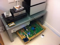
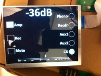
Here it is. I am amazed at how quiet it is - you have to stick your ear right up against the tweeter to just hear something - and its unboxed so I am talking about hum as well - zero, zip, nada and I am operating it in single ended mode. The PGA2320 operates at unity gain with an attenuater in front of it for gains less than 0 dB, and above that the opamp gain is increased up to a max of 31.5 dB. If you feed it from a low source (CD player e.g.), the peak noise is at about -25dB gain - where the attenuater is about mid point. The max gain on my implementation is +15 dB. Control via rotary encoders and display driven off an ARM MCU.
PGA2320 - A highly recommended device IMO.
http://hifisonix.com/ovation-sca-1/
Attachments
Last edited:
Not the fellow I was thinking of. If I have time I'll try to find a cite.
Is this MIT'er getting angry about the physics taught at a superb liberal arts institution down the street?
Now a three foot cube of 1/4" plexi-glass being pumped down is a video I'd like to see!
Appendix B in your first link is what I meant.
Quote: Originally Posted by scott wurcer
Yes, there is a level 3 JFET that AFAIK no free SPICE implementation has, and no manu that I know of extracts these models.
Agilent Advanced Design System has it:
<http://edocs.soco.agilent.com/display/ads2009/LEVEL3+MOD+Model+%28Level-3+NMOD+MOSFET+Model%29>
Unluckily, it's far away from "free" in every aspect.
regards, Gerhard
Yes, there is a level 3 JFET that AFAIK no free SPICE implementation has, and no manu that I know of extracts these models.
Which Spice implementation has "level 3" JFETs?
Agilent Advanced Design System has it:
<http://edocs.soco.agilent.com/display/ads2009/LEVEL3+MOD+Model+%28Level-3+NMOD+MOSFET+Model%29>
Unluckily, it's far away from "free" in every aspect.
regards, Gerhard
Simons puzzle reminded me of my days at college. At the instant the switch is closed the lecturer would say...... now calculate the current in L and this that and the other... and so on.
What do you guys think would be the outcome of this. Maybe its a silly question, maybe not. I'd be interested to hear your thoughts even if my maths won't keep up
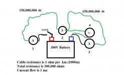
The green wire is 300,000km in length. If we say (for arguments sake) that the "speed" of electricity in a copper wire conductor approaches the speed of light, then, by conventional thinking it would take one second for electricity to travel down the wire. In the diagram, the four meters are all near the observer who is located by the battery and switch. The 300,000km of wire goes its merry way looping back to the observer at the midpoint. Under steady state conditions a current of 1ma flows. Each ammeter would show 1ma with the voltmeter at midpoint showing 150 volts.
So... on closing the switch, what would each meter read. Say you took 10 readings each spaced 100ms apart. What would you see ?
What do you guys think would be the outcome of this. Maybe its a silly question, maybe not. I'd be interested to hear your thoughts even if my maths won't keep up
The green wire is 300,000km in length. If we say (for arguments sake) that the "speed" of electricity in a copper wire conductor approaches the speed of light, then, by conventional thinking it would take one second for electricity to travel down the wire. In the diagram, the four meters are all near the observer who is located by the battery and switch. The 300,000km of wire goes its merry way looping back to the observer at the midpoint. Under steady state conditions a current of 1ma flows. Each ammeter would show 1ma with the voltmeter at midpoint showing 150 volts.
So... on closing the switch, what would each meter read. Say you took 10 readings each spaced 100ms apart. What would you see ?
Attachments
Quote: Originally Posted by scott wurcer
Yes, there is a level 3 JFET that AFAIK no free SPICE implementation has, and no manu that I know of extracts these models.
Agilent Advanced Design System has it:
<http://edocs.soco.agilent.com/display/ads2009/LEVEL3+MOD+Model+%28Level-3+NMOD+MOSFET+Model%29>
Unluckily, it's far away from "free" in every aspect.
regards, Gerhard
Check with Mike Engelhardt at Linear Technolgy, the developer of LTspice. I would not be shocked if it was in there somewhere. If not, I would not be surprised if he was willing to put it in.
BTW, unless I'm mistaken, the issue we are talking about here is the transition region between linear and saturation regions, not the matter of sub-threshold conduction in JFETs. I have often wondered about sub-threshold conduction in JFETs, but have only heard it discussed in the context of MOSFETs.
Cheers,
Bob
I think it was that model Yamaha, or maybe another that had wide IF bandwidth switching function....good for listening to FM broadcasts at home, but no good as an FM off-air monitoring receiver. In the wide bandwidth mode, over regulations modulation sounded fine, but not representative of what most listeners were hearing.
Don't get me started on DAB+....
Dan.
It does auto switching between wide and narrow IF depending on recieved signal conditions... but it is pretty easy to defeat the auto switching function and lock it on which ever you want. Then, there are the T-85 and CT-7000, too. [www.fmtunerinfo.com]
Thx-RNMarsh
Last edited:
Yes that transition region is precisely what I am interested in. In short-channel devices saturation is very fuzzy, to say the least --- and yet these are the high-performance devices of particular utility.BTW, unless I'm mistaken, the issue we are talking about here is the transition region between linear and saturation regions, not the matter of sub-threshold conduction in JFETs. I have often wondered about sub-threshold conduction in JFETs, but have only heard it discussed in the context of MOSFETs.
Cheers,
Bob
My current software, for which I paid a healthy sum years ago and requires a lot of tricks to patch around its numerous bugs (and has long been unsupported), decides that you get the triode region for a while, then abruptly switches to a linear slope representing a one-number output conductance. Needless to say this doesn't work very well, although I suppose I should be grateful for something that eventually drives me over to the bench.
I've considered, but not yet implemented, a level 3-like model based on some of the math functions available, and fitting to observed databook curves.
One preamp, actually an MC stepup gain of 20dB device, I actually did build, while trying to please certain audiophile conceits while still yielding good measured performance. The need for better models became apparent when it worked exactly backwards in its effects! When I swapped some things the idea did work, but the models could not be tweaked to conform to the measurements.
And yes, it sounded good, even doing my best to discount favorable bias toward one's own . In fact I listened to LPs with it quite happily until I tried to move the kludge a little and shorted out one of the power supplies. Having fallen off the horse I set everything aside and moved back to another cartridge and turntable
I did get the courage to bring it back up, and it appears damage was minimal --- but by then I was an order-of-magnitude less interested in catering to the aforementioned conceits, and would do it differently now.So... on closing the switch, what would each meter read. Say you took 10 readings each spaced 100ms apart. What would you see ?
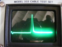
Attached is a Time domain reflectometer picture. Now is the cable open or shorted?
Attachments
Check with Mike Engelhardt at Linear Technolgy, the developer of LTspice. I would not be shocked if it was in there somewhere. If not, I would not be surprised if he was willing to put it in.
BTW, unless I'm mistaken, the issue we are talking about here is the transition region between linear and saturation regions, not the matter of sub-threshold conduction in JFETs. I have often wondered about sub-threshold conduction in JFETs, but have only heard it discussed in the context of MOSFETs.
Cheers,
Bob
From our users manual. The MESFET work quoted was adapted for ordinary JFET's and again you would be on your own in extracting the parameters. Brad, there is a paper that achieved almost perfect match to real Toshiba devices with one tanh equation. I gave up playing with it because I could not figure out how to insert the legal function range checking without going into the guts of whatever simulator you were using.
Divide by zero simulation aborted
51 JFET3 Model
The JFET3 model in Adice5 was developed from several standard JFET models and improves the accuracy of the simulated channel current (and output resistance) across all regions of operation in comparison with the older JFET1 model (see JFET1 Model). The DC channel current is modeled with the hyperbolic tangent model of Curtice [36], and the subthreshold equation updates the original model of Chang [37]. The new model also includes features such as mobility degradation due to the gate field and drain voltage induced threshold voltage modification. The JFET3 model improves the temperature dependence of the gate leakage current and the subthreshold current. The drain and source resistances have scaling equations for straight and concentric layouts and have temperature coefficients.
W. R. Curtice, "A MESFET Model for Use in Design of GaAs Integrated Circuits," IEEE Trans. Microwave Theory Tech., vol. MTT-28, pp. 448-456, May 1980.
C. T. M. Chang, et al., "A Subthreshold Current Model for GaAs MESFET's," IEEE Electron Device Letters, vol. EDL-8, No. 2, Feb. 1987.
Last edited:
LTspice documentation:
Z. MESFET transistor
Symbol Names: MESFET
Syntax: Zxxx D G S model [area] [off] [IC=<Vds, Vgs>]
[temp=<value>]
A MESFET transistor requires a model card to specify its
characteristics. The model card keywords NMF and PMF specify the
polarity of the transistor. The MESFET model is derived from the
GaAs FET model described in H. Statz et al., GaAs FET Device and
Circuit Simulation in SPICE, IEEE Transactions on Electron Devices,
V34, Number 2, February, 1987 pp160-169.
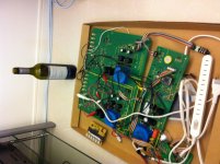
Here it is.
Whoa (© jneutron), nothing like the sight of a full-size main board in the morning. Unity case must also be your thing.
That display is a beaut.
LTspice documentation:
If you read the Cadence docs the ALPHA parameter is the one, it's not clear from the LT docs. I don't have access to my IEEE library, but it would be a great service to the community if someone sorted this out once and for all. Maybe just calling a BF862 an nMESFET and playing with ALPHA will do the trick. Fat chance
.BTW you lose several oher parameters in doing this.
Last edited:
Mooly: voltage instantaneous (with a single switch). Current, there and back time.
Hmm... me no understand
So that means meter "4" (the voltmeter) would show 300 ? volts at the instant of switch on. Full voltage because no current is yet flowing. Wouldn't that mean its registered a "change" in an event (throwing the switch) quicker than the speed of light.
I really don't get it.
After 0.5 second, what would meter 4 show ?
and what would meter 1,2 and 3 record ?
What am I missing
Since you only have one switch, the potential difference exists before you close it (assuming the setup was there more than a few seconds in advance!). It takes a second before the far end "realizes" that the switch is closed, then another second before the current reaches the switch end. There's probably a complication because of loop area, but I'm ignoring that for the sake of simplicity.
- Status
- Not open for further replies.
- Home
- Member Areas
- The Lounge
- John Curl's Blowtorch preamplifier part II